
Buckle up, y’all; here comes a long one.
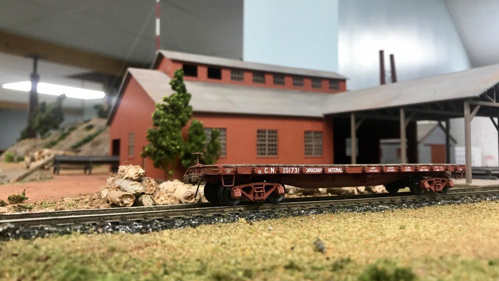
In my last update, I mentioned that my scratch-build of one of CN’s 1929 built “Group C” flat cars was drawing to a close. I am happy to report it is indeed now complete, sans a retainer valve. As I could never discern the valve’s location on the prototype, my thoughts were that it would be better to leave the part off the model entirely rather than guess and find out later it was put in the wrong location.
Let’s begin.
In 1929, CN had 300 46’1″ flat cars built. What makes these 300 cars unique was they were the first flat cars CN had built to its own design. Until this time, all of the flat cars on the CN roster were a hodge-podge of assets inherited from its predecessors, from varying builders and designs.
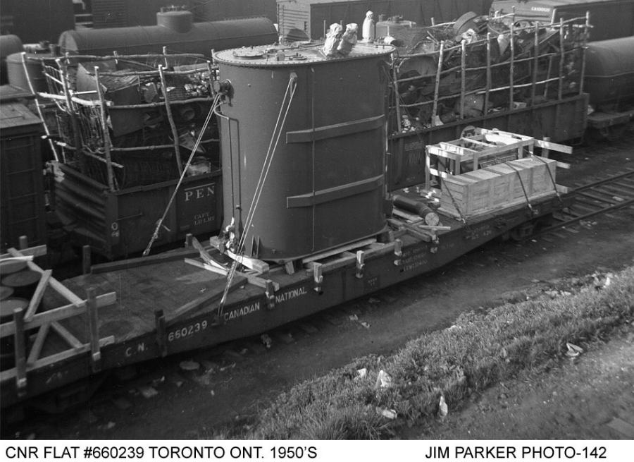
I learned about these “Group C” cars while working on my CN “A-3” cars: scratch-bashes of two Tichy kits; they are featured in the same two 1994 articles by Stafford Swain in CN Lines (issues V5N3 and V5N4.)
Using the supplied drawings, I cut out a piece of .060″ V-Groove styrene to act as the car floor, and from a sheet of .030″ plain styrene sheet, cut out the side and centre sill plates. The centre sill of the car was then assembled as a sub-assembly, using strip styrene for the bracing, spacing and to simulate the rivet plates. I also added the rivets to the center sill at this point using Archer Fine Transfers, as I knew I wouldn’t be able to get at it after all of the details and side sills were installed.
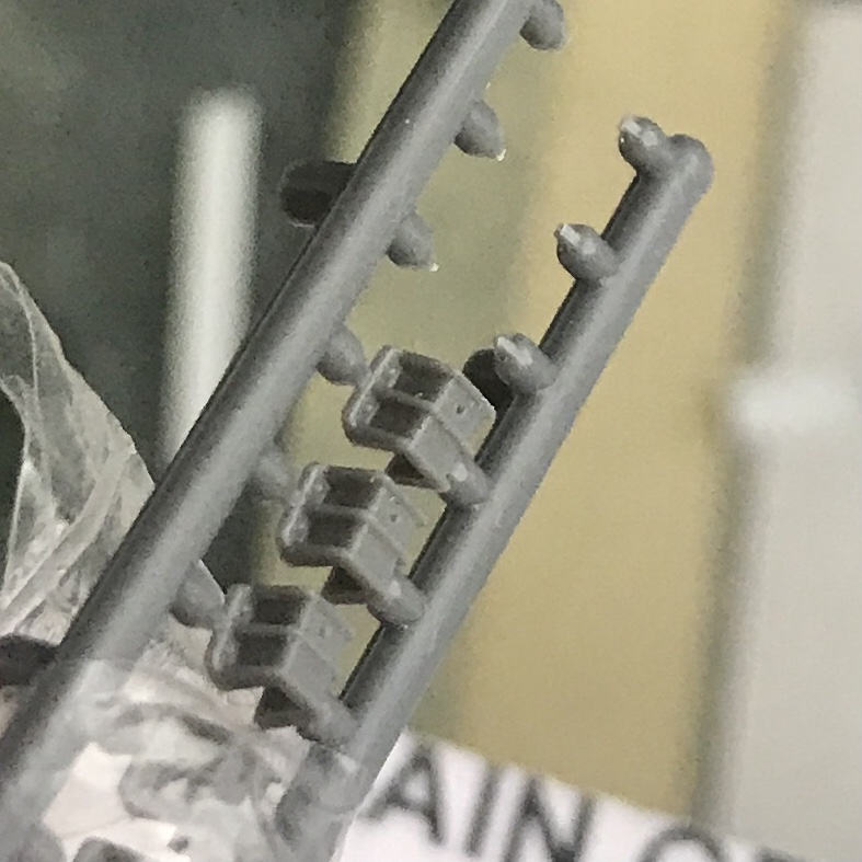
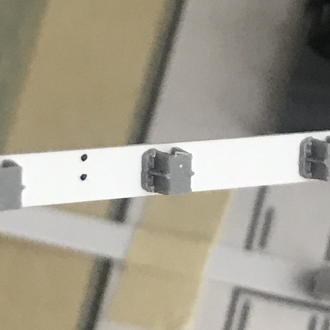
I took a piece of plain paper, taped it to a piece of glass and then measured out the distance between each stake pocket for the car side sills. I then taped the side sills onto this and glued each Titchy stake pocket to the side sill using the paper as a guide. After the glue had ample time to dry and the styrene had time to properly re-solidify from the solvent glue, I used a #17 blade to take all of the “U bolt” details off the stake pockets. I used the #17 blade to notch a horizontal line across the middle of the face of the stake pocket. Utilizing the notch in the middle of the front of the stake pocket as a guide, I used my flush cutters to cut a roughly 45-degree angle from the center of the face of the stake pocket down to the bottom “foot.” This mimics the prototype more accurately than the Titchy pockets that come from the package. After the stake pockets were completed, I set them aside.
[As you can imagine, the entire process for the stake pockets was an absolute nail-biter because one mistake would render the whole side sill junk… I took a lot of time to make sure I did this cleanly and accurately. I luckily only made one small mistake, which was easily hidden with some Mr. Surfacer 500 painted over the dent in the sill and sanded flat.]
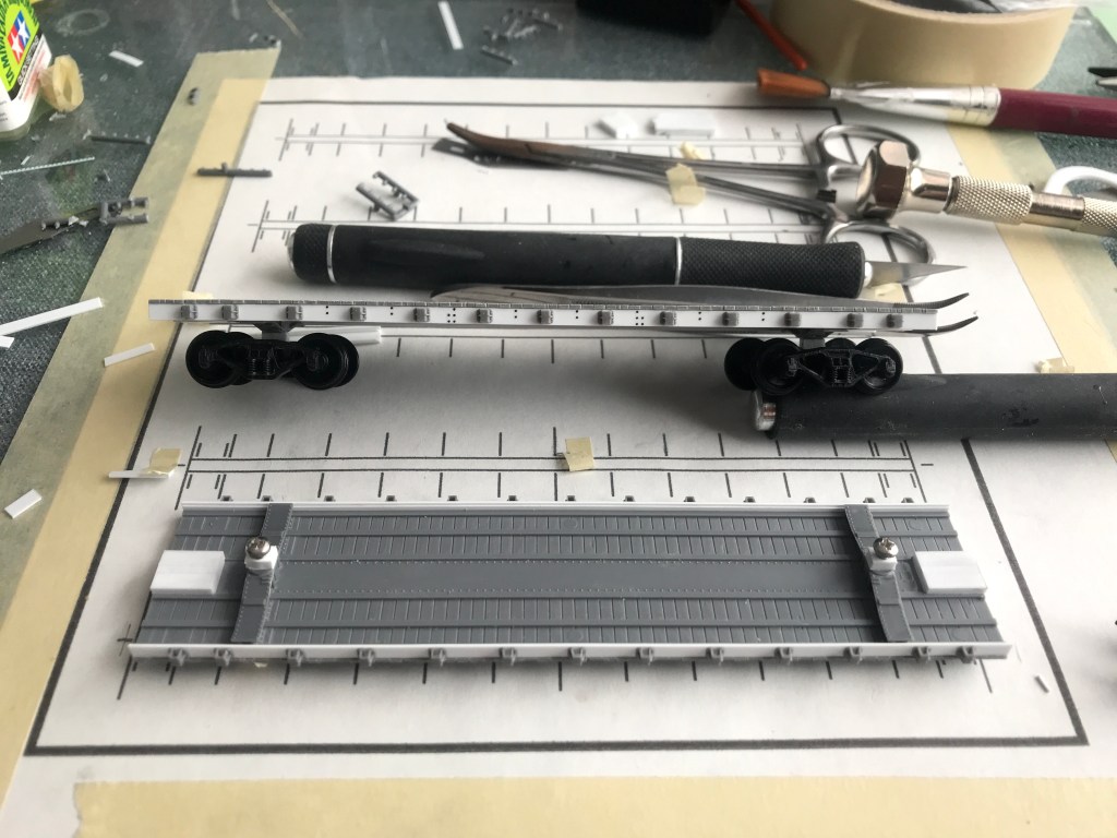
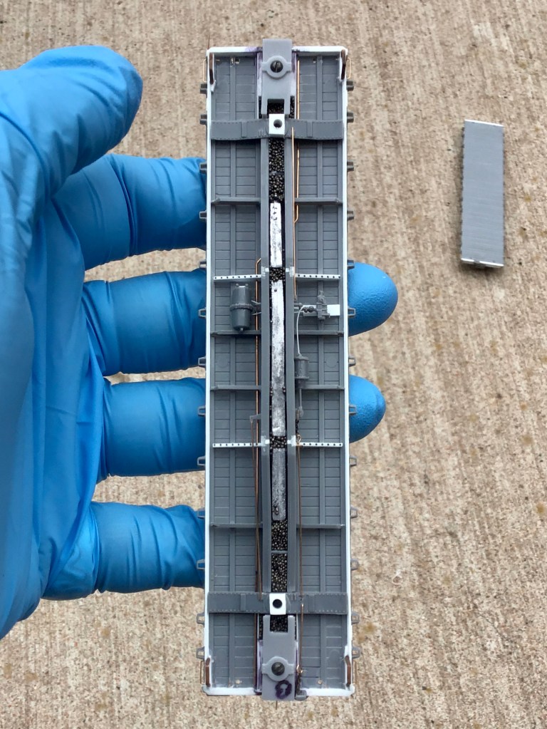
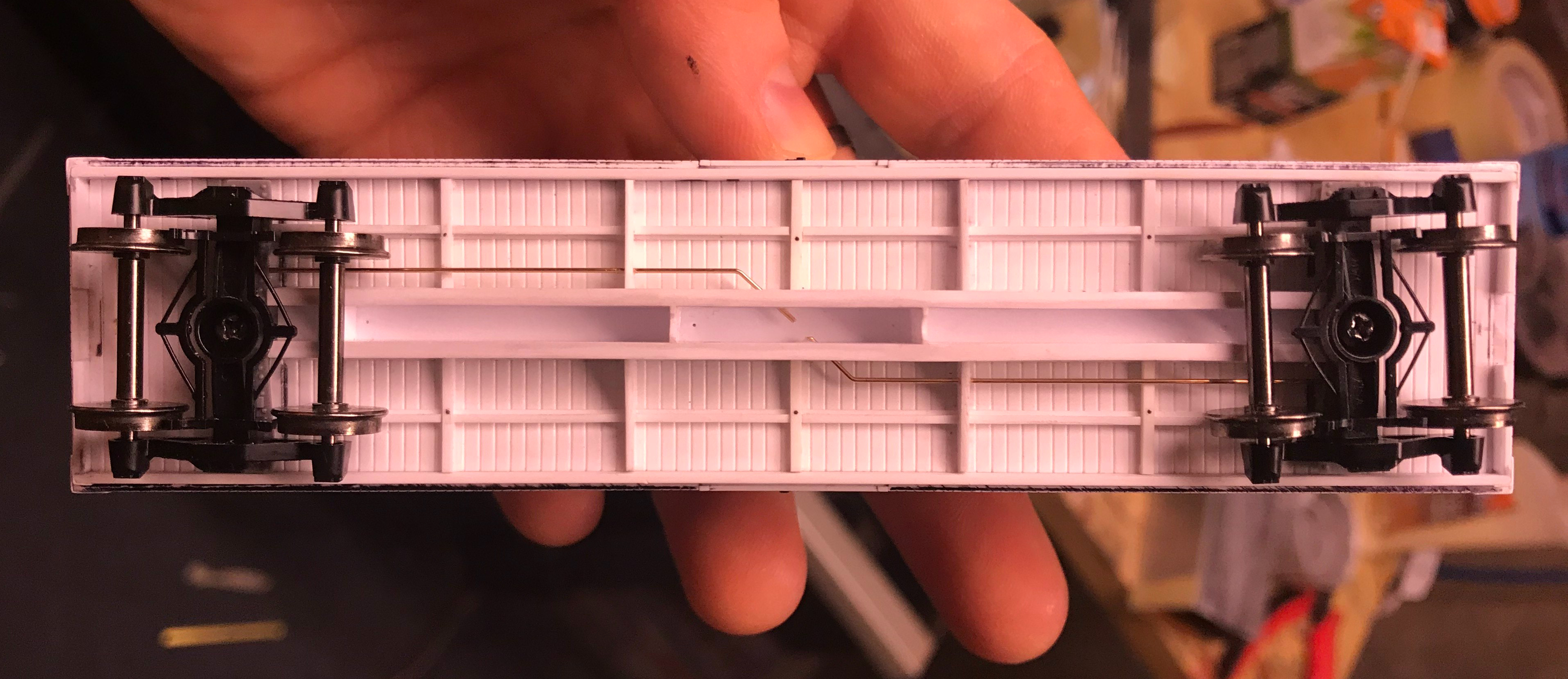
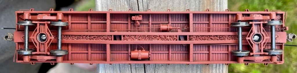
Before installing the centre sill, I drilled out two holes for each truck at a spacing of 35’9″. I then screwed two Titchy Bolsters to the car floor and cemented them in place. Once the cement dried, I fit the scratch-built centre sill snugly between the bolsters, centred it to the car and glued it in place.
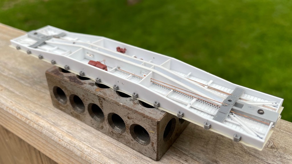
I installed Z-bracing to the car floor parallel to the centre sill. The z-bracing was scratch-built by threading two 1×3″ and one 1×2″ piece of styrene through a homemade jig and glued with Tamiya Ultra Thin. Then I used my JMC Micro Saw to cut out notches to fit in the four more prominent cross members, pre-drilled to accept the train line.
The article didn’t include any photos or drawings of the underframe, so I studied the rivet patterns on the car sides from prototype photos and similarly built flat cars to conclude the location of the cross members and brake components.
The fourteen Z-shaped cross members were installed using leftover z-bracing. I notched out one end of each cross member with a 400 grit PC board file to fit flush against the centre sill. I then ran a sanding block vertically down the side of the car floor to ensure there was no overhang into where the side-sills would be installed.
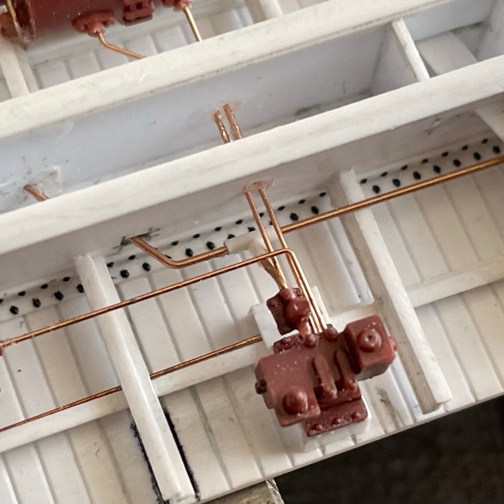
Next, I installed brake levers fabricated from strip styrene into the sill and the Cal-Scale brake parts. This required me to modify the triple valve mount with a file and make hangers for the air tank from phosphor bronze wire.
Before installing the brake piping and rods, I scratch-built a slack adjuster from scrap pieces of styrene and used a Titchy NBW to simulate the bolt into the associated brake lever. The airlines were installed with .010″ wire and the rods with .0125″ respectively. I used Titchy turnbuckles cut in half to act as the clevis on the connections to the brake levers, and scale chain was used between the brake cylinder and associated rod. The last thing I installed on the underframe was the train line, using .015″ wire and a scratch-built “t-valve” from styrene rod, connecting the train line to the triple valve.
While this might seem like a disjointed way to go about building the under-frame of the car, I did it in this order because I knew once I put the car’s body sills on, I wouldn’t have much room to work on the small parts. I had to be careful not to box myself in.

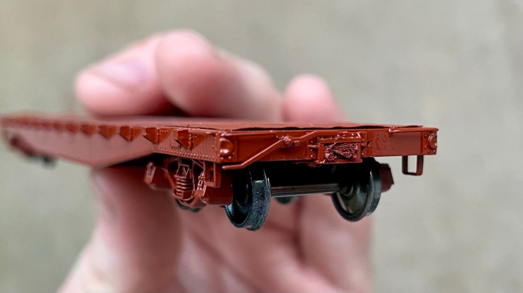
With the under-frame assembled, I next installed the side-sills. To get an excellent 90-degree joint, I used a machinist square on its fat edge to push the sill flush while the glue set. The car ends were installed using 1×12″ scale strip styrene and reinforced from behind with 1×10″ to prevent warping.
The joints were sanded clean, and then corner irons were installed with strip styrene.
I used a single edge razor blade to shave the poling pockets off some spare Titchy boxcar ends I had lying around. I glued the poling pockets on top of the corner irons and purposely used a liberal amount of styrene cement so they would melt into the corner irons to look like one solid part.
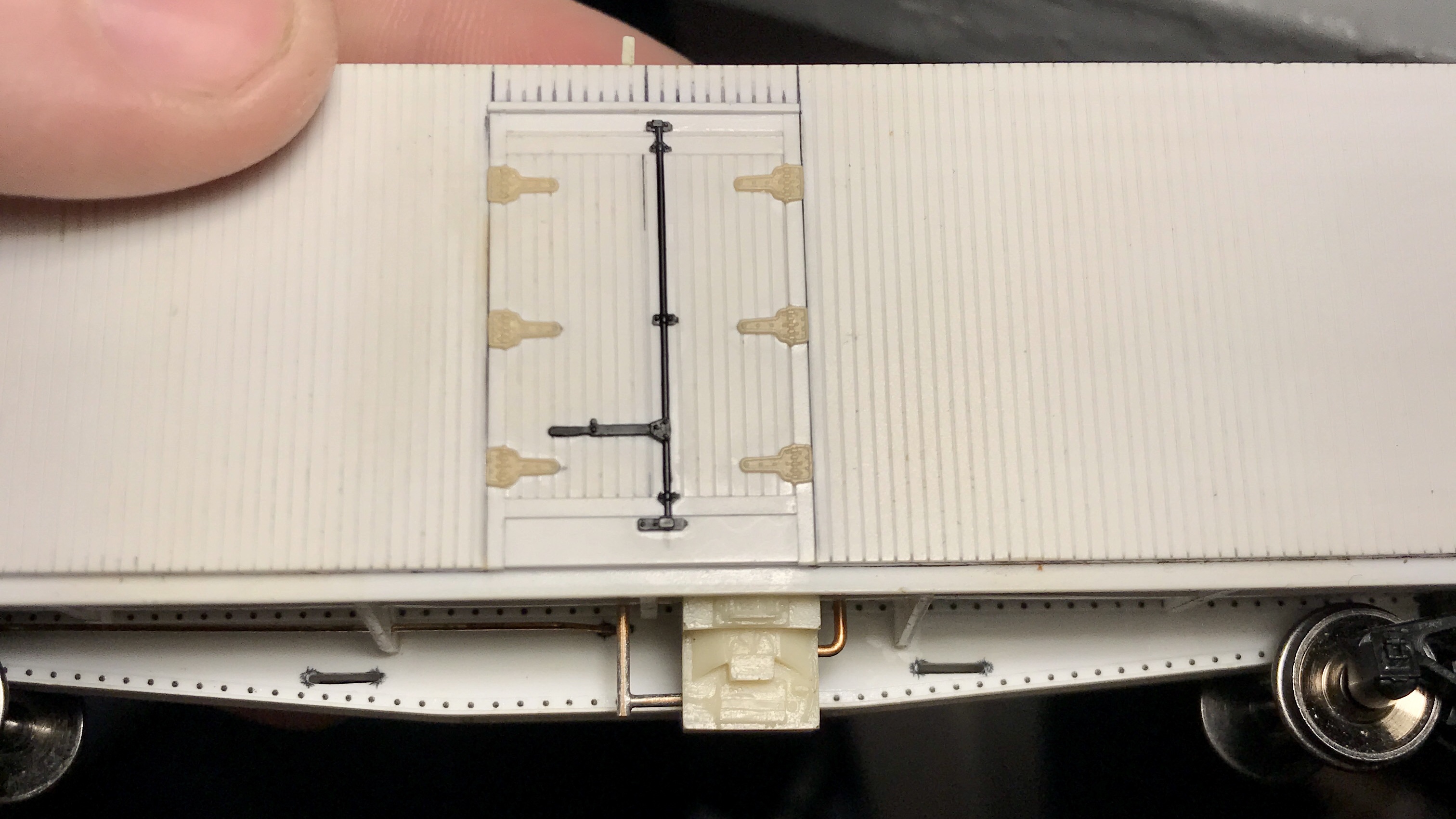
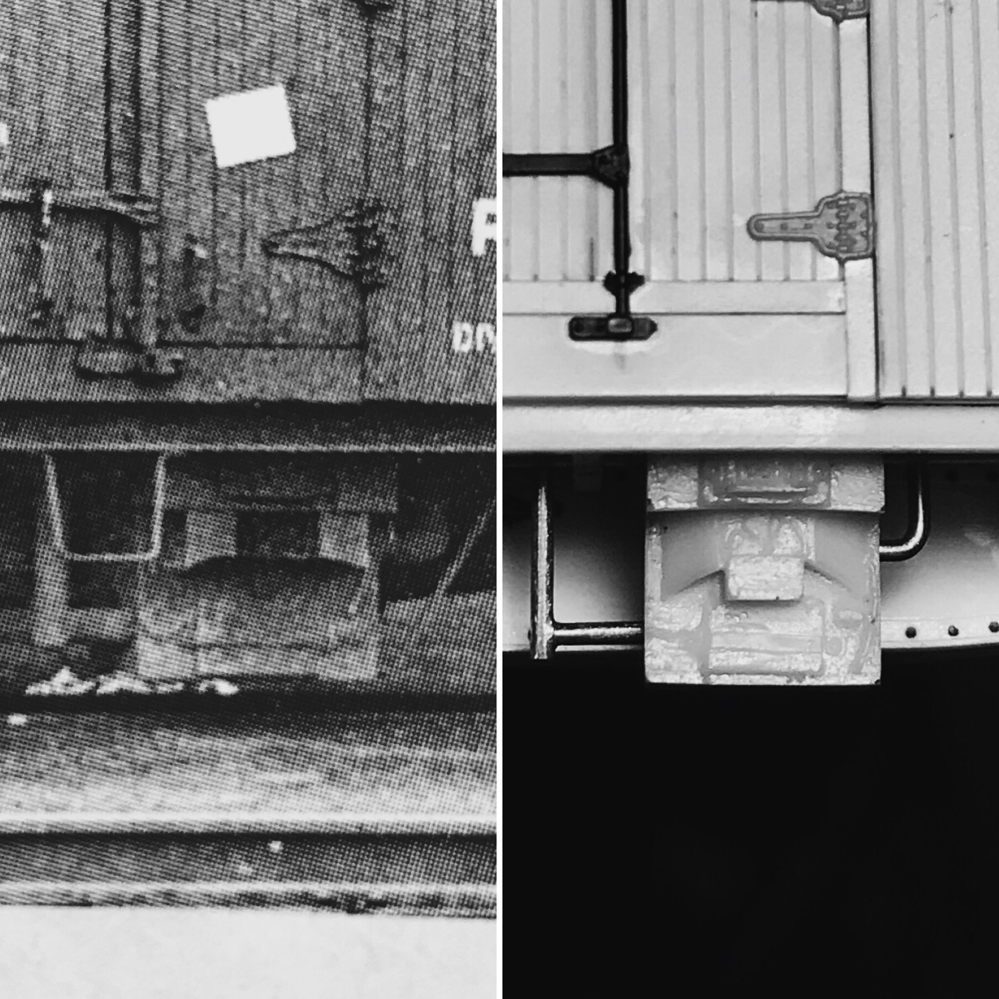
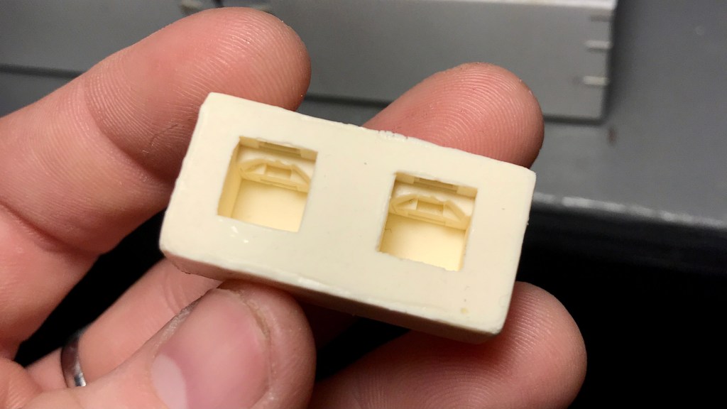
With the general shape of the car completed and the underframe more or less entirely assembled, it was now time to install the Smokey Mountain scale coupler pockets.
I measured the centre of the car ends and then cut notches for the width of the draft gear box with my JMC saw. I scored the inside of the car end that was to be removed with a #11 blade and then snapped it out with my tweezers.

The Smokey Mountain coupler pockets were fitted into the car ends, the screw-hole marked with a pencil and then drilled out and installed. As the prototype had a slightly wider buffer block than the Smokey Mountain product, I used a 1×3″ styrene strip on each side of the buffer block on the car end. This also covered up any visible slop between the draft gearbox and the notch cut out for it.
The brake wheel and its mechanism were installed on the car end. I used the Titchy rachet part but decided to upgrade to a brass Precision Scale brake wheel.
The Yarmouth Model Works Carmer Cut Levers were then installed. I used a 4×4″ square of styrene to mount the cut lever, and put a Titchy NBW on top of it to simulate a bolt.
The grab irons were drilled out and installed with .010″ wire, my new go-to over .0125″ as I find .0125″ looks large when painted.
The A-Line stirrups were held over a candle and flattened out straight, re-bent to match the prototype and then installed by first drilling into the bottom of the side sill before being glued in place.
Before painting, I installed all the remaining rivets onto the car using Archer Fine Transfers and the articles drawing as a guide and then installed the Tahoe Model Works Trucks. I also at this point installed the weight into the center sill, which was lead shotgun shot given to my by a friend.
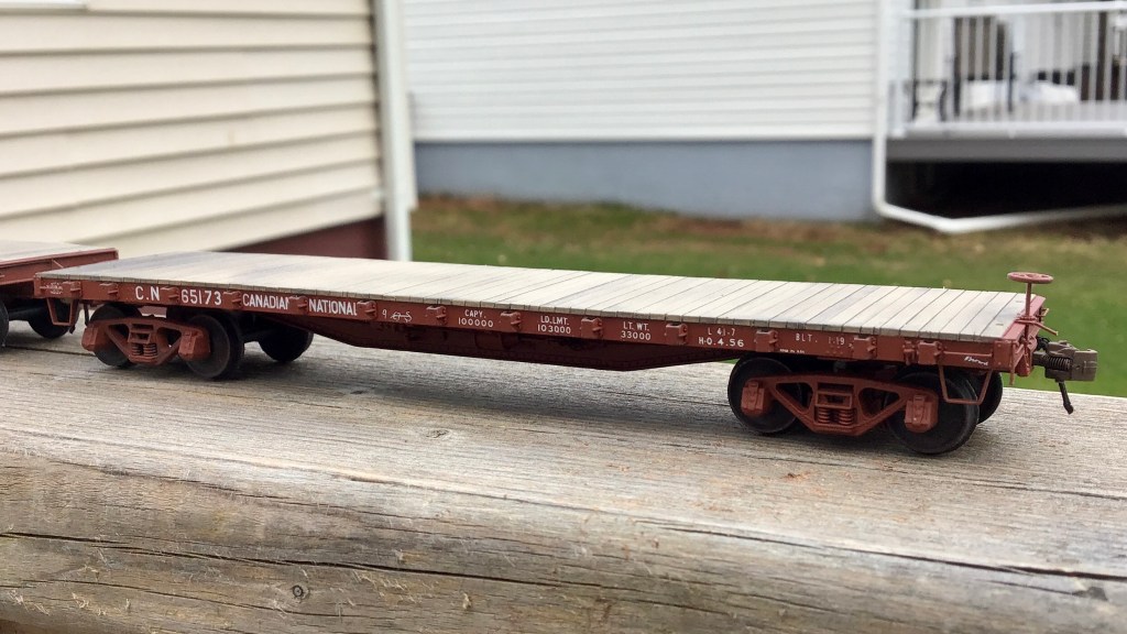
The car was then primed with Tamiya Fine Surface Primer and allowed to dry overnight. I used my regular mix of Vallejo paints to paint the model CNR #11 red. Future floor polish was used to prepare the model for decals.
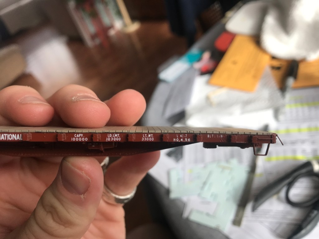
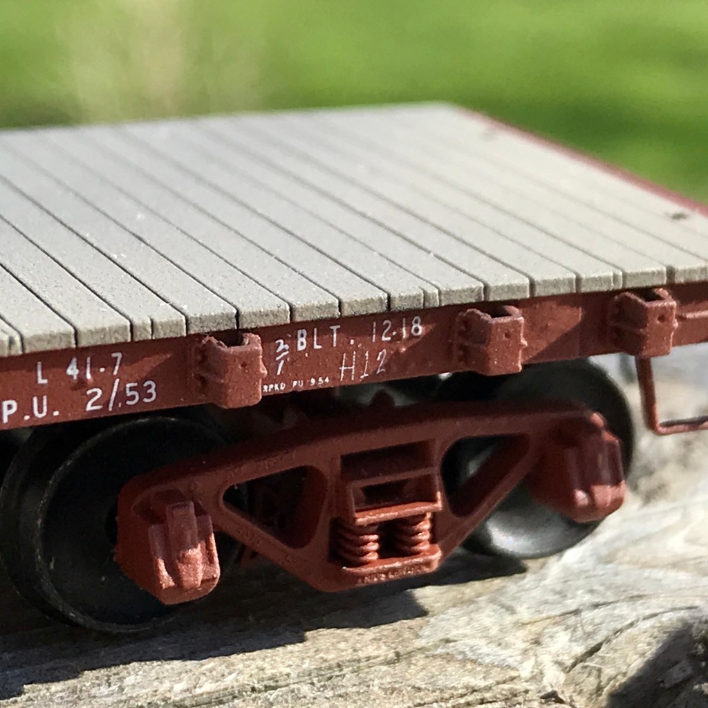
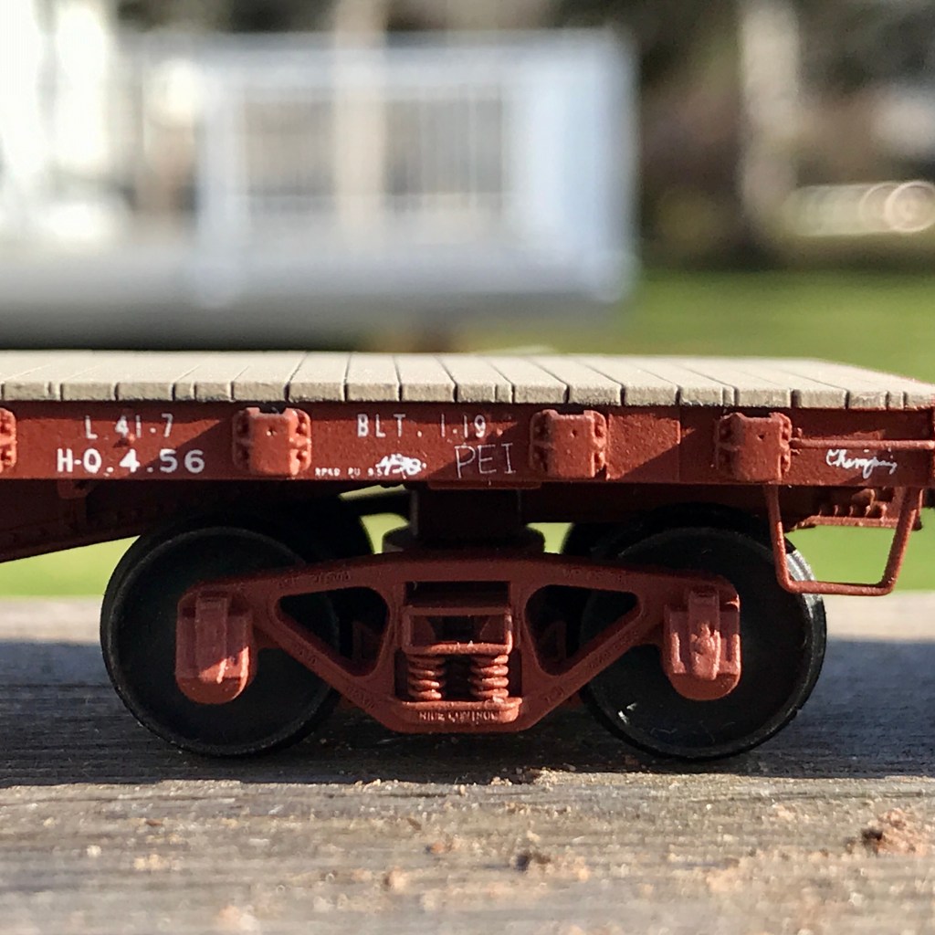
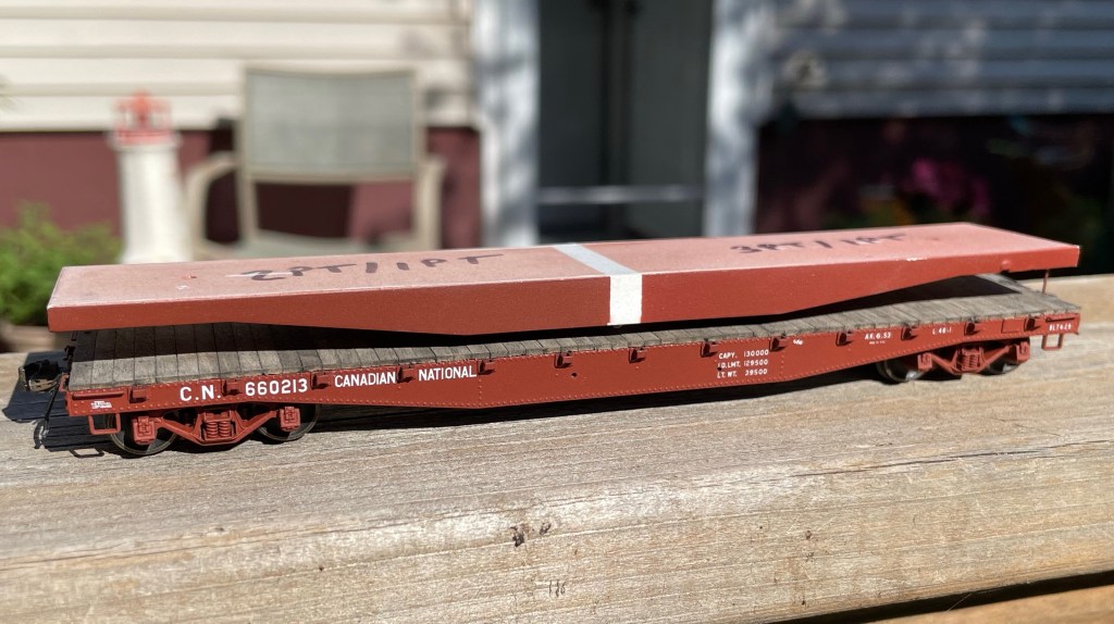
Black Cat CNR Flat Car decals were applied with the car being lettered for road number #660213, coated again with future floor polish. The car was matte-coated with Vallejo Matt Varnish.
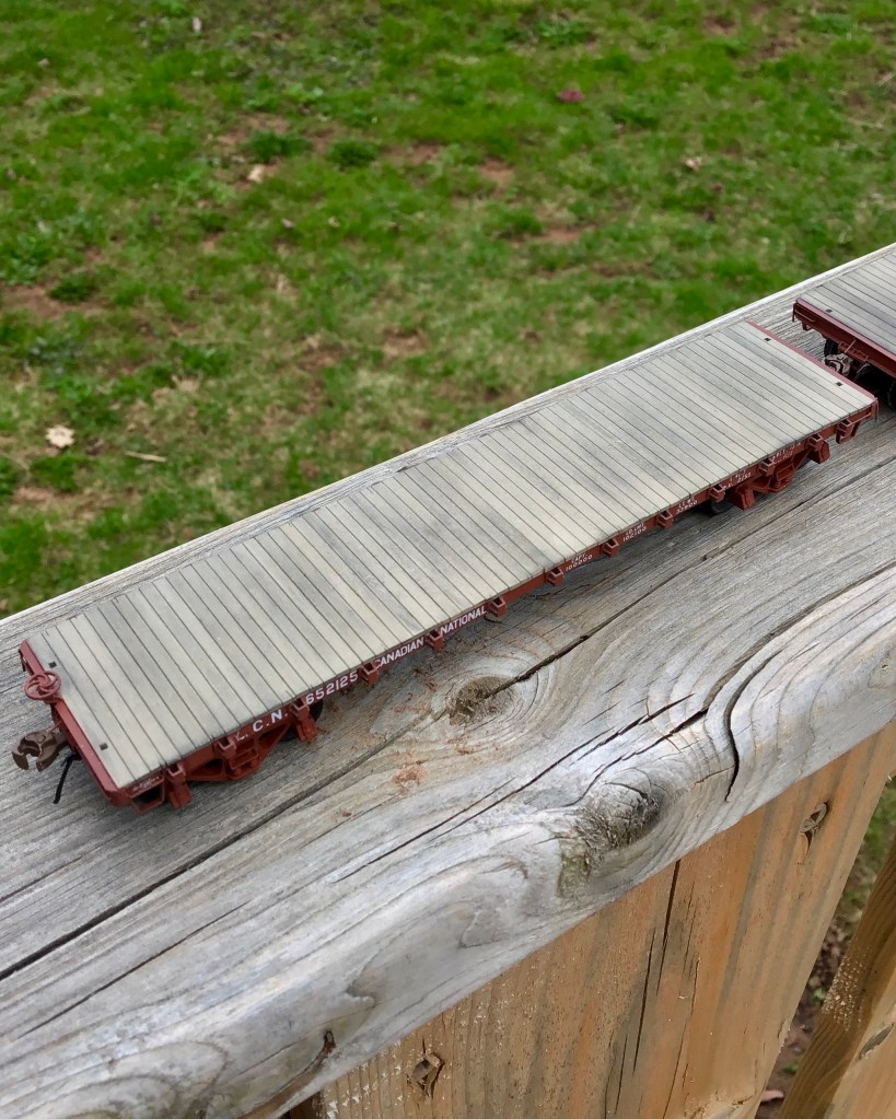
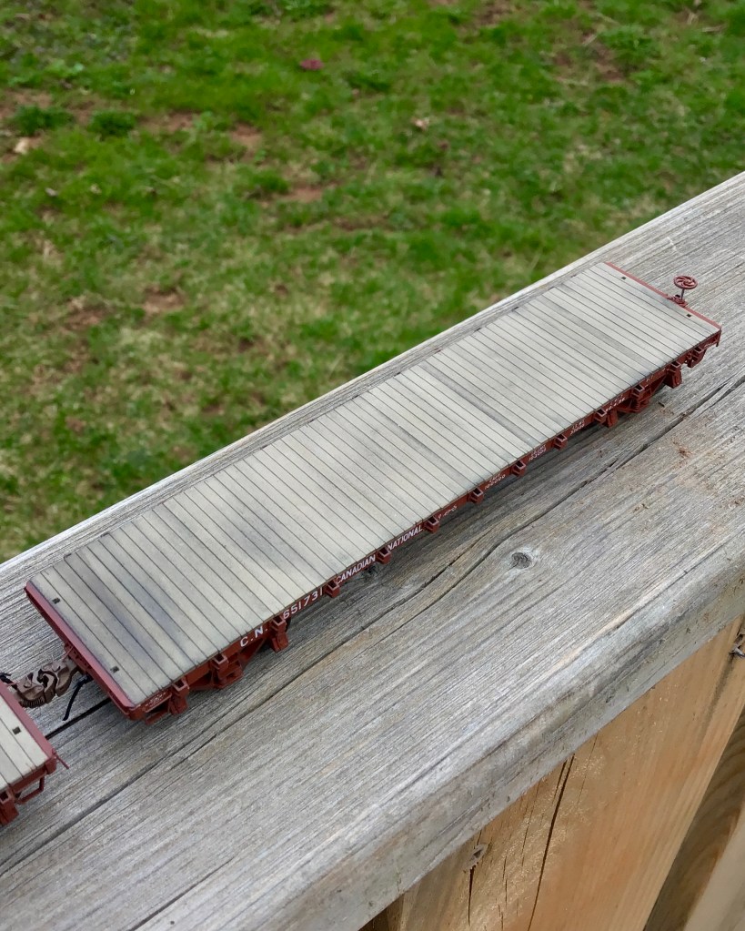
It was then time to install the car’s decking; for this, I used 3×8″ scale lumber from Northeastern Scale Lumber cut into 9′ lengths. I began by first installing a single board on each end of the car, ensuring they were dead centre to the car. After the (15 minute) JB weld had dried overnight, I set a ruler against the boards previously installed on each end and on top of the stake pockets; this created a dead straight line between each back of the car and allowed me to install each board dead center as well. This is an aspect of the build I spent a lot of time thinking out before tacking, as I knew that if the boards waned and weren’t straight, I would not be happy. It turned out to be a straightforward process in the end.
Lastly as far as the decking installation was concerned, I drilled out the holes for the end stake-pockets and squared them up with a #11 blade.
With the decking installed, I took a sanding block with 400 grit sandpaper on it. I sanded the deck to level it out a bit and get rid of any fuzzies from the wood I didn’t get before installing. I stained the wood decking on the car with a light mixture of India ink and isopropyl alcohol.
I decided I wanted to try simulating the nails that hold the decking to the car floor. For this, I went to a pharmacy and asked for some of the smallest hypodermic needle tips they had. I measured out where each “line” of nails would be on each end of the car and then used the hypodermic needle against a ruler to install over 400 “nails” into the car deck. I then gave the deck another coat of stain, sanded it, and then stained it one final time. The result is subtle, but I think it turned out well as the nails in a wood deck aren’t that noticeable on the prototype once the deck becomes dirty.
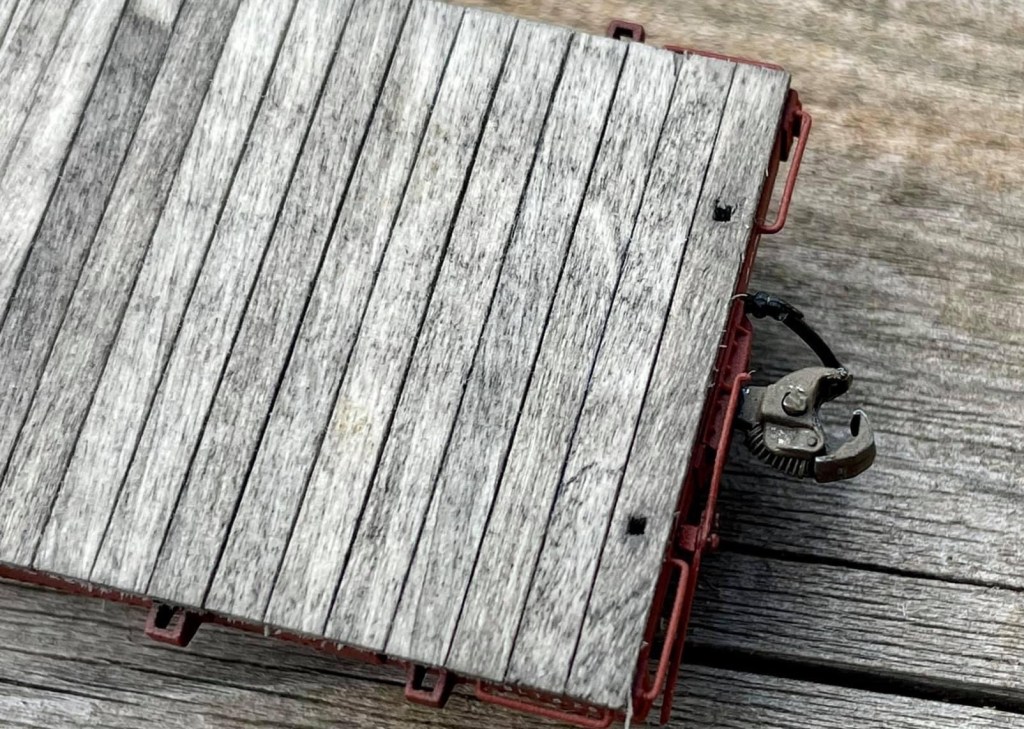
Finally, Hi-Tech Details rubber air hoses were installed on each end of the car along with Kadee #158’s.
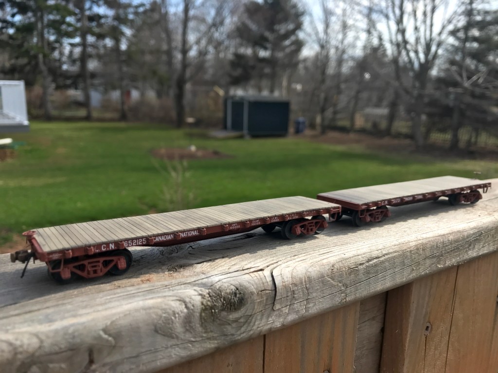
That’s a wrap! A long and complicated build is finally completed, and I am very proud of the end result. It is my intent to eventually have this model judged toward an NMRA car-building merit award. Find below a parts and materials list for this build.
Next up, finally more work on that pesky CNR wood-reefer scratch-build (and maybe a new not-so-much scratch built reefer project…..)
CM
RAW MATERIALS:
Evergreen Scale Models:
- .060” V-Groove Siding (#14060) [12”x24” sheet, special ordered]
- 1×2” HO Scale Strip Styrene (#8102)
- 1×3” HO Scale “ “ (#8103)
- 1×4” HO Scale “ “ (#8104)
- 1×6” HO Scale “ “ (#8106)
- 1×8” HO Scale “ “ (#8108)
- 1×10” HO Scale “ “ (#8110)
- 1×12” HO Scale “ “ (#8112)
- 2×12” HO Scale “ “ (#8212)
- 4×4” HO Scale “ “ (#8404)
- .030” Sheet Styrene (#9030)
- .040” “ “ (#9040)
Northeastern Scale Lumber:
- 3×8” HO Scale Lumber (#3811)
Plastruct:
- .010” Styrene Rod (#90850)
Tichy Train Group:
- .008” PB Wire (#1100)
- .010” “ “ (#1101)
- .0125” “ (#1106)
- .015” “ “ (#1102)
COMMERCIAL PARTS:
- A.A.R. 22” Air Hoses, x2 / Hi-Tech Details (#6038)
- AB Brake System, x1 (Plastic) / Cal-Scale (#283)
- Barber S-2 50 Ton Trucks / Tahoe Model Works (#113)
- Bolsters, x2 / Tichy Train Group (#3069)
- Brake Wheels – 6 Spoke, x1 (Brass) / Precision Scale Company (#31117)
- Carmer Cut Levers / Yarmouth Model Works, x2 (#404 & #401)
- Scale Draft Gear Boxes / Smokey Mountain Model Works, x2 (87-DP-401-GY)
- Stake Pockets, x26 / Tichy Train Group (#3006)
- Stirrup Steps, x4 / A-Line (#29000)
- Turnbuckles, x4 / Tichy Train Group (#8021)
- Vertical Brake Staff & Support, x1 / Tichy Train Group (#3003)
- 7/8 Boxcar End, x2 / Tichy Train Group (#3058) [Used to harvest four poling pockets]
- 33 Inch Semi-Scale All-Metal Wheelsets / Tangent Scale Models (#137)
SCRATCH-BUILT PARTS:
- Side sills, x2. [.040” Sheet Styrene]
- End sills, x2. [2×12” & 1×10” Strip Styrene]
- Corner gussets, x4. [1×12” Strip Styrene]
- Grab irons, x8. [.010” Phosphor Bronze Wire]
- Center sills, x2. [.030” Sheet Styrene]
- L brackets for centre sill. x4. [1×6” & 1×4” Strip Styrene]
- Center sill foot plates, x2. [1×6” Strip Styrene]
- Brake rods, x2 [.0125” Phosphor Bronze Wire]
- Brake lines, x3. [.010” Phosphor Bronze Wire]
- Retainer valve line, x1. [.008” Phosphor Bronze Wire]
- Verticle buffer plates, x4. [1×3” and 1×2” Strip Styrene]
- Wood deck boards, x60. [3”x8” Scale Lumber cut into 9’ lengths with a NWSL Chopper II. Installed individually on car floor.]
- Z-Bracing [1×2” and 1×3” Styrene fed through a scratch-built jig and glued into a “Z” with Tamiya Extra Thin.”
- Crossmembers, x10. [Same process as Z-Bracing.]
- Crossmembers, x2. [1”x4” Strip Styrene]
PAINTS / FINISHES:
- Brown / Vallejo Model Air (#71.105)
- Camo Medium Brown / Vallejo Model Air (#71.038)
- [2pts #71.105 + 1pt #71.038 = CN #11 Red]
- Fine Surface Primer, Oxide Red / Tamiya (#87160)
- India Ink, Super Black / Speedball
- Nato Black / Vallejo Model Air (#71.251)
- Polyurethane Matt Varnish / Vallejo (#26.651)
- Revive It Floor Gloss (Future) / Johnson
DECALS:
- Canadian National Flat Cars / Black Cat Publishing (#289)
- Freight Car Chalk Markings / National Scale Car (#D135)
- Railcar Rivets / Archer Fine Transfers (#88025)
ADHESIVES / WEIGHT:
- 15 Minute Epoxy / JB Weld
- Medium CA / Mercury Adhesives
- Extra Thin Plastic Weld / Tamiya
- Lead Shotgun Shot [Used as weight] / Western Metal