It has been a while, and I’ve wanted to deliver a minor update before a larger one.
I’ve been taking a break from the hobby and blog to focus on my personal and professional life. The past year has been quite busy, in a mostly positive way. Finally, the dust is beginning to settle in the sense that I can start to once again devote some mental real estate to my favorite hobby! I am starting to gear up the model train of thought.
This time away has given me a lot of opportunity to refine my interest in PEI railroading in the creative sense. Before taking a break, I became interested in the 1:64 scale, and I still find this an exciting way forward. I have arrived at two particular areas of interest and will plan two layouts simultaneously.
The first layout is a short-term goal, the planned Vernon River modules in 1:64 rather than 1:87. I have most of the equipment needed to accomplish this, and I just have to get down to the building part. No more buying is required for this layout.
The second layout is a long-term affair requiring a basement, which I do not yet have. This will be based on PEI, the mid-1970s up to the abandonment (1989) era prototype. Bram Bailey’s photos from his “Canadian National Atlantic Region In Color,” some Steve Hunter photos, and other video footage I have in the vault are a big inspiration. Rapido’s release of the RSC-14 has allowed this to be a viable option and goal to work towards. I have seven RSC-14s on order, numbers 1750-1756, some of which will be custom numbered by Rob Arsenault. Over the past year, I have been pre-ordering and tracking down relevant rolling stock and hoarding it away as it arrives.
I can’t promise a regimented schedule of updates, but I will do my best. There are some exciting developments on the way.
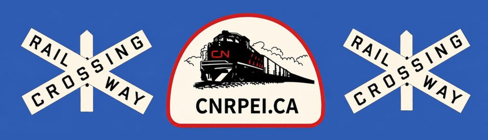
For a fun size comparison, two 36′ CNR Stock Cars; a 1:87 Westerfield kit next to a 1:64 Simon Parent kit.
When I started considering S-scale as a viable adjustment for the Vernon River plan, I went straight to the top of the Canadian 1:64 food chain for advice. Trevor and David took me in and sorted me out with everything I needed to know in the world of 1:64, what equipment I needed, and where to get it and I am very grateful for their help. It also turns out S-Scalers are apparently hoarders, so I didn’t have to go terribly far to find 90% of the rolling stock and power I need for the entire layout.
One of the places they sent me, however, was to Simon Parent to get my hands on one of his flat resin Stock Car kits. Simon didn’t have any left but was kind enough to track one down for me from someone he knew selling one.
The kit fully assembled, prior to priming and painting.
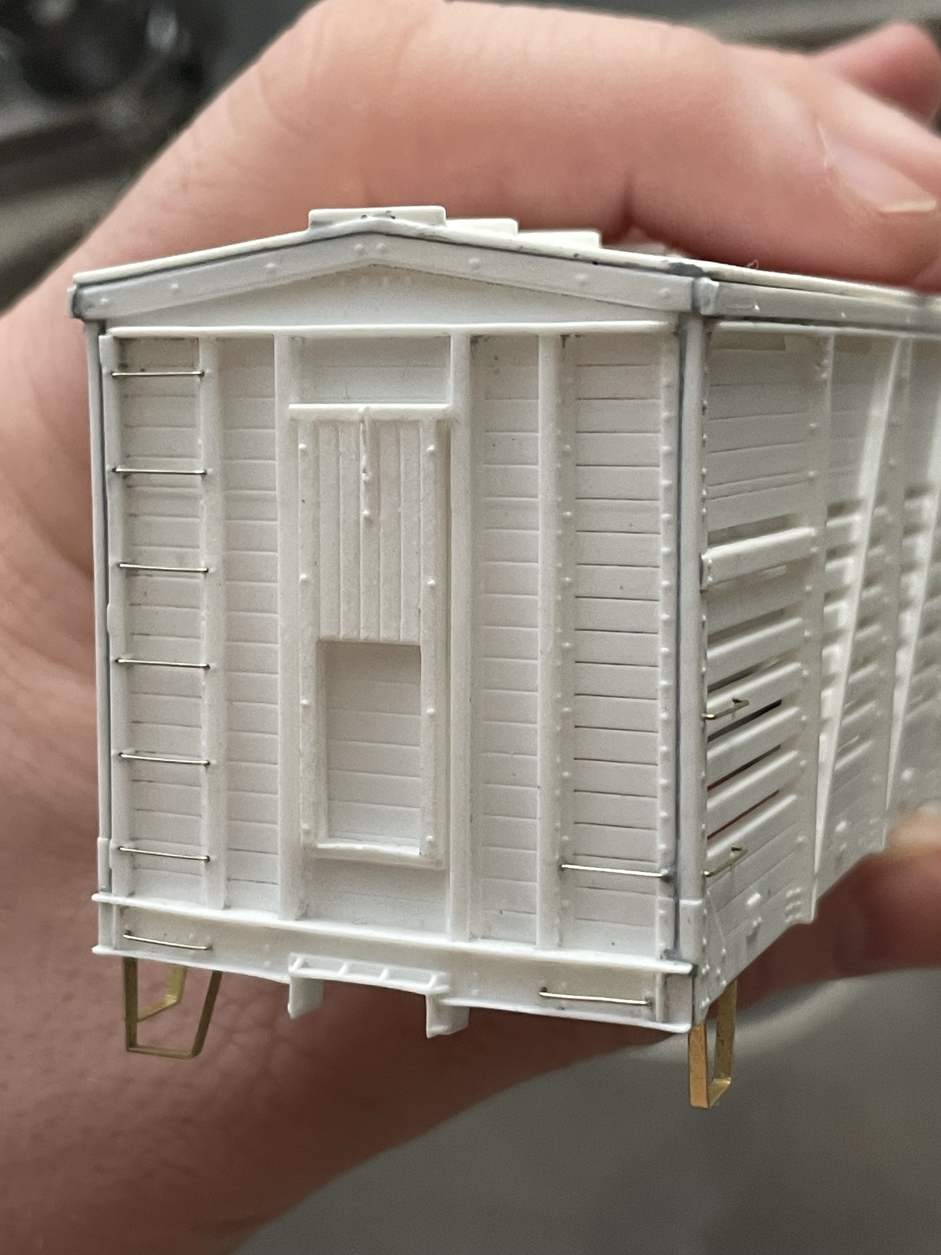
The kit’s castings were very clean and crisp and the kit included all parts required for success except for trucks. Luckily, Simon is in the business of 3D printed trucks and sold me some very beautiful sprung trucks that are accurate for the car along with custom wheelsets.
Before:After: (B End)After: (A End)Mr. Surfacer is hands down one of my favourite hobby products. It’s magic. Filling in the gaps created by shrunken castings, as you see above, required zero sanding. I just apply the product liberally, let it dry for roughly 20 minutes and then aggressively rub the excess off the model with a cotton swab saturated with isopropyl alcohol. Repeat until satisfied. Messy? Yes. Satisfying? Also yes!
In my initial experience, this build was a breeze compared to anything I’ve done in 1:87, and though I had a minor issue with shrunken side castings, a sanding block and some Mr. Surfacer solved that with very minimal heart-ache.
Painting the car, I used my regular mix of Vallejo paints to get the CNR boxcar red, prepped for decals with Future and after decal-ing with the included decal sheet, I sealed it off with another coat of Future and some Vallejo Matt Varnish.
CN #170249 in all it’s completed glory.
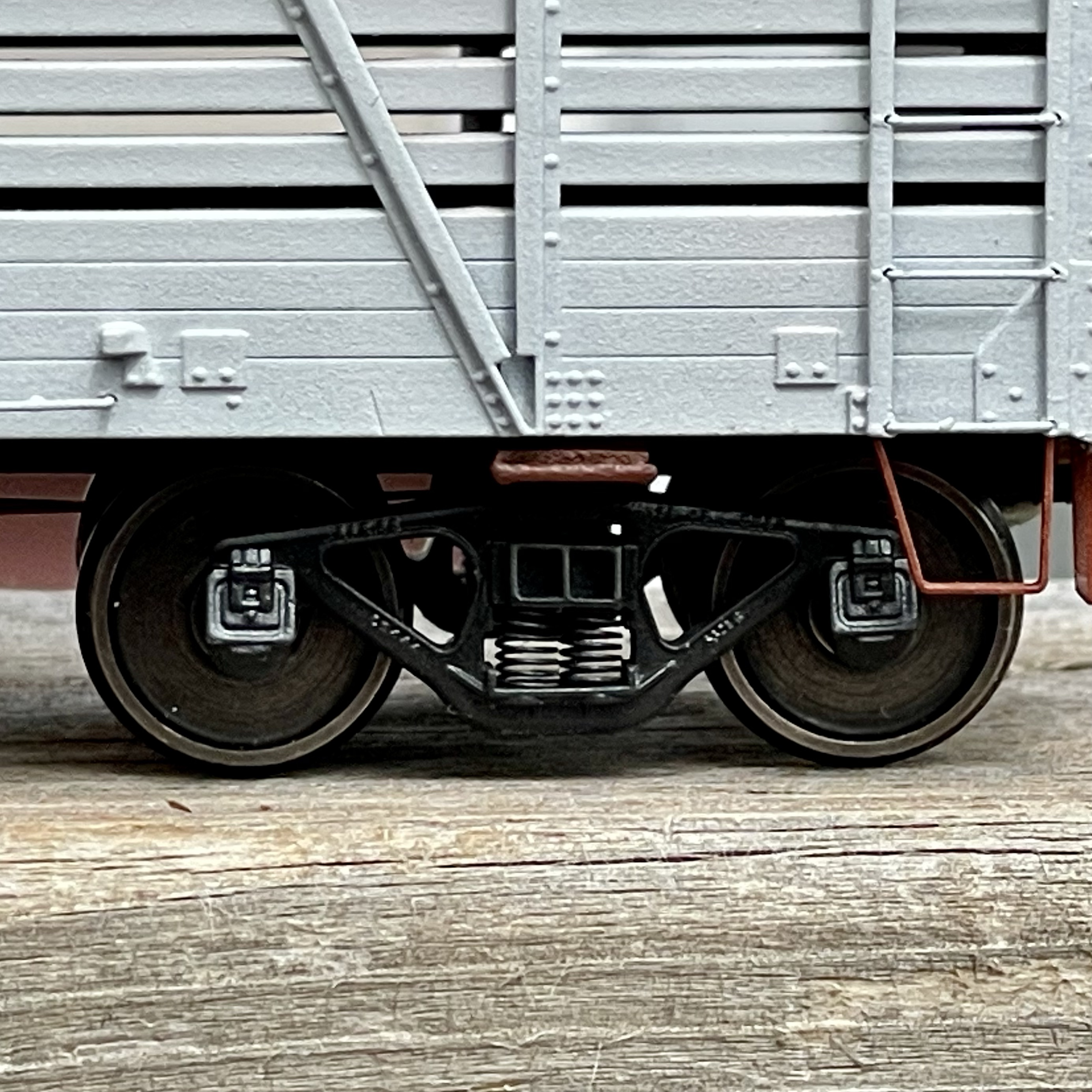
One thing I’m not entirely sold on in the world of S-scale is the oversized #802 Kadee couplers. I think what I may do is design and 3D print a coupler pocket that mirrors the footprint of an 802 pocket, but accepts a (1:87 scale) #158 whisker coupler, and then just continue to use Kadee #158’s.
Somewhere in the mail is a brass River Raisin 44 Tonner, brass CNR combine kit as well as a wide array of other 1:64 goodies. I’ll be sure to do an ‘unboxing’ post when the package arrives.
Over the past six months or so, while the blog hasn’t been particularly active, and I have not had as much time as I’d like to physically sit down and build, I have been quite active in terms of layout planning. When I say layout planning, I mean more so figuring out the future for Vernon River and my modelling interest in PEI in general.
Something that never wavers for me is my interest in island railroading, and if I’m being honest, I really don’t have much interest in railroading be it historically or in the modelling world unless it’s PEI-related.
Something that I have determined through many long nights of research over the years, is that I have two very distinct eras and locations of interest for modelling PEI.
These eras and locations can be described as follows:
PEI’s transition era. 1947 – 1952ish. Eastern PEI. Small GE switchers (44 and 70 Ton), 36′ wooden freight cars, mixed passenger trains, riveted tank cars. That sort of thing.
PEI’s twilight years. 1980-1989. Western PEI. RSC-14s, modern equipment, abandoned stations, everything runs as an extra, three-car trains with two locomotives and a PSC van. That drift.
What I have realized, through conversations with others and my own research is that these two described eras of interest are vastly different. And as different as they are, fundamentally, they are better represented by different scales due to the availability of model equipment, and in my opinion best represented by different approaches to modelling in general.
What I’ve decided, by the availability of equipment, is that I can better represent my transition era prototype of Vernon River if I simply backdate my era ten years from 1957/58 to 1947/48 and move from a 1:87 scale to a 1:64 scale. A 70 Tonner becomes a 44 Tonner. There are now more wooden cars than steel cars. Not much else changes. The larger size will allow me to enjoy my modules in more detail, and provide a more accurate experience. Of course, compression will need to occur in the track plan, but not much.
What else I have decided is that Vernon River will remain a set of 1:64 modules, and nothing more. I will be able to set up these modules where I currently live, as well as take them to shows to show off. But I don’t intend to expand Vernon River into a full-size layout anymore.
As a house looks more and more within the realm of possibility, I have had to take time to really consider what a long term layout will look like, and what I will do for a full-size operational basement layout. For when that time comes, I’ve decided I will move back to 1:87 scale, where I can best represent PEI with equipment suited for the 1980s. I have pre-ordered seven Rapido RSC-14s in anticipation of this, some of which are custom numbered, for a full complement of the PEI assigned units of 1750-1756.
In summary, I have determined the best ways to represent PEI in a model format using the space I have access to, and in terms of equipment availability. My dedication to modelling and researching PEI railroading knows no set scale, and will always follow the best path to an accurate representation of history.
Rejoice; I have finally put a lid on this three year on-and-off project. #55699 lives. See below for more in-progress and completed photos.
Merry Christmas, everybody. I hope all of my followers were able to celebrate generally to at least some degree. Mine was low-key, which is the norm for me anyway.
My Christmas Day miracle was applying the window glazing to this Eastern Road Model’s Double-Ended Transcona Shop Snowplow just before midnight and finally being able to call it finished. I was not finished before Christmas as I had set out in my last post, but on Christmas nonetheless. I’ll take it.
To continue my previous post, with most of the work on the plow’s body completed, I turned my focus to the cupola.
The large grab irons around the perimeter have been installed using .010″ Titchy PB wire. The Yarmouth Model Works eyebolts are visible, and as you can see I have ensured a uniform clearance from the cupola roof by using strip styrene shims between grab and cupola as the glue dried
The first thing I tackled was the large grab irons around the perimeter of the cupola roof. I thought this would be a lot more fiddly than it turned out to be, and it only took about 20 minutes. I used Yarmouth Model Works photo-etched eye bolts and .010″ Tichy PB wire for the grabs themselves with pieces of styrene strip between the grab and cupola roof to provide a uniform clearance while gluing them into place.
Next, I added the stove stack, horn and headlights.
The stove stack, headlights and horn have all been installed. This view will provide better context to what was done to the headlight. There is a headlight installed on the opposite end of the cupola as well
The stove stack was modified to be of the coal-burning variety by using a piece of 1/8″ styrene tube cut in half. It is a bit oversized, and I may replace it with brass at some point down the road, but not now.
The horn required only a simple hole, but the headlights were a little more complicated. The Pyle headlight was a Detail Associates part, and I glued the full headlight to a larger piece of styrene to keep it in place, while I used a razor saw in a mitre box to cut only the front of the headlight off, which was then glued to the cupola.
Next, couplers were installed. I used Kadee scale-head couplers with a short shank. I filed around the base and the top and bottom of the coupler shank (where the whiskers attach) to allow more freedom of movement in the box. I then painted the couplers and installed them using a piece of 1/8″ styrene tubing to fill the hole in the coupler box and keep the couplers in place. I used a tiny drop of CA to adhere the tube into the hole, let it set, and then painted Mr. Surfacer 500 on and around the tube before filing it all flat.
The Kadee short-shank coupler installed into the coupler box before being primed over. Visibile is the 1/8” styrene rod, and you can see traces of the Mr Surfacer 500 in and around the rod.
I taped off the couplers and then gave the boxes another quick shot of primer and let them dry.
Before painting the model, an under-frame for the weights and trucks to ride on was required. Using CAD and the measurements provided in the kit’s instructions, I drew the under-frame and cut it out of .040″ styrene mechanically with a Cricut Maker. I modified Tichy body bolsters to be only 1/8″ high from the under-frame and cut the ends off to compensate for the now lower swing of the trucks. These plows ran super low to the rails, which creates additional considerations when modelling them.
While looking for truck bolsters in my spare parts, I found a full under-frame from a Tichy flat car kit. I decided that although it wouldn’t necessarily be accurate (the plows did retain their K-brakes for their entire service life, however), it would be a fun touch, so I added it to the blank under-frame.
The underframe. You can see the filed down and cut short truck bolsters, as well as the full under-frame salvaged from a Tichy flat car kit.
The prototype used special arch-bar trucks with a 4’2″ wheelbase. The closest I could find were Tahoe Model Works’ 5-foot wheelbase arch bar trucks (TMW-111/211). To match the prototype, I used Intermountain 28″ diameter replacement wheelsets. I threaded the screw-bosses in the 3D printed part of the bottom of the plow-body and then test fit the underframe to the plow.
At this point, it was time to paint. I used my usual mix of Vallejo paints for the body and cupola to get CN boxcar red. The inside of the cupola is painted a sea-foam green, while the seats were painted gull grey with black cushions. The stove-stack was painted aluminum, and the interior of the headlight housing was painted with glossy silver. A coat of gloss was applied with Future floor wax, and I set the model to dry for a few days before applying decals.
Paint, gloss and a road number applied. Visible is the seafoam green cupola interior and painted seats. Repack dates were added after this photo.
The decals were applied using scraps of leftover Black Cat Decal boxcar sets. Using prototype photos of plows that were kept captive to PEI in the mid-1950s, I determined that most plows at this time only had road numbers and bearing repack dates, so the plow reflects that.
#55699 all wrapped up and ready for the rails.
After painting and decals, all that was left was to install the window glazing inside the cupola. I used .005″ clear styrene by Evergreen for this, with Micro Krystal Klear to adhere it to the inside of the cupola.
Topside view of #55699.
All in all, I enjoyed this kit, but it was not for the faint of heart or easily frustrated. I’d give anybody who attempts this build the following advice: you’ve already spent a lot of money on this kit, don’t cheap out and use the Micromark rivet decals. The Archer rivets, in my experience, look much nicer. In retrospect, if I had to build the model again, I would use them instead of the Micromark decals. That’s not to say the Micromark decals look bad; they could just look better, is all. Lesson learned.
Calvin
PS: Your very own Transcona Shops Double-plow kit can still be purchased. Body here and cupola here. I have no connection to Eastern Road Models and make no guarantees of their products or the service Shapeways provides.
PPS: The next project is brought to you by the letter “S” and the number “64”…
Steve Hunter’s very own Double-ended plow, built from his own kit. Photo and model by Steve Hunter.
It’s been a busy and just plain overwhelming summer and fall, which has not left me with a lot of time or capacity to build.
But, with things calming down and signs of winter starting to appear, I figured that it might be an appropriate time to build the Eastern Road Model’s CNR Double-ended Snowplow kit I’ve been sitting on for a few years.
For those unfamiliar, Eastern Road Models was the moniker Steve Hunter used for his PEI prototype-focused Shapeways 3D printed model shop.
CN built a small handful of these Double-ended plows at the Transcona shops in the 1930s, and while they could be seen elsewhere in the system from time to time, I am all but sure they were built with PEI in mind; they could be seen on the island right up until abandonment.
The body and cupola are shown as primed before any detailing. Yes, my bathroom has the best lighting in the house once the sun goes down.
The body and cupola are supplied as separate purchases, and the rest is up to the modeller to source and more or less figure out.
Assorted photos showing the progress I’ve listed below.
Sparing a novel, essentially up to this point in the build, what I have accomplished is as follows:
Prepared the Shapeways parts by leaving them in an ultrasonic bath filled with a mixture of Simple Green HD and water.
Sanded the body of print lines and removed any excess wax material from the printing process.
I drilled for the grab irons and other necessary holes.
I primed the body and cupola.
Applied Micro-Mark rivet decals to the body and cupola (has to be closing on 1000 rivets).
Bent all grab irons from scratch, including the drop grabs, using .010” PB wire.
Installed the brake wheel and staff.
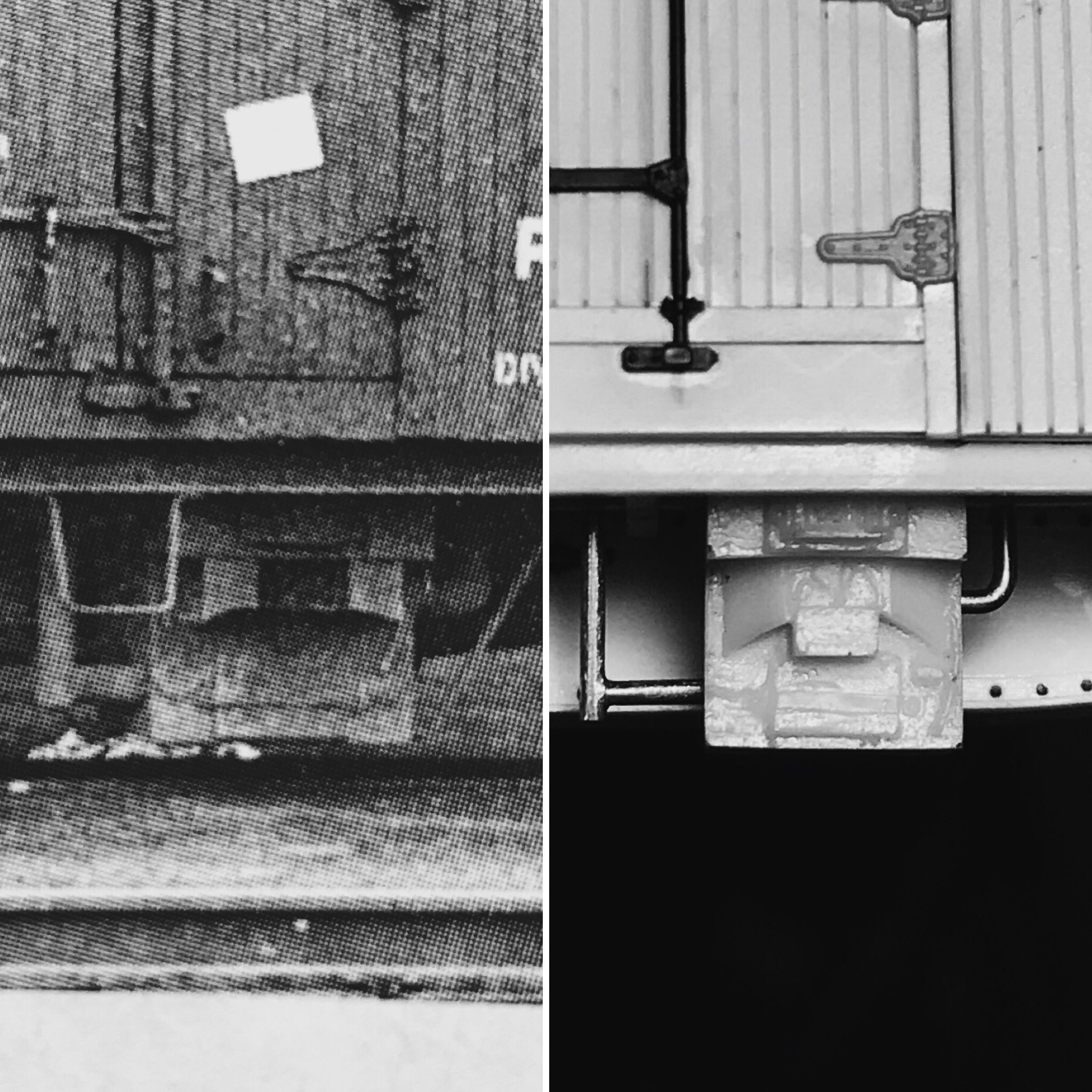
Installed the wire, receptacles and snow shields for the snowplows power connections with the locomotive.
Installed hinges on the journal box access hatches using Grandt Line reefer hinges.
All that remains is the installation of the roof grabs around the cupola, stove stack, horn, headlights, paint, decals, couplers.
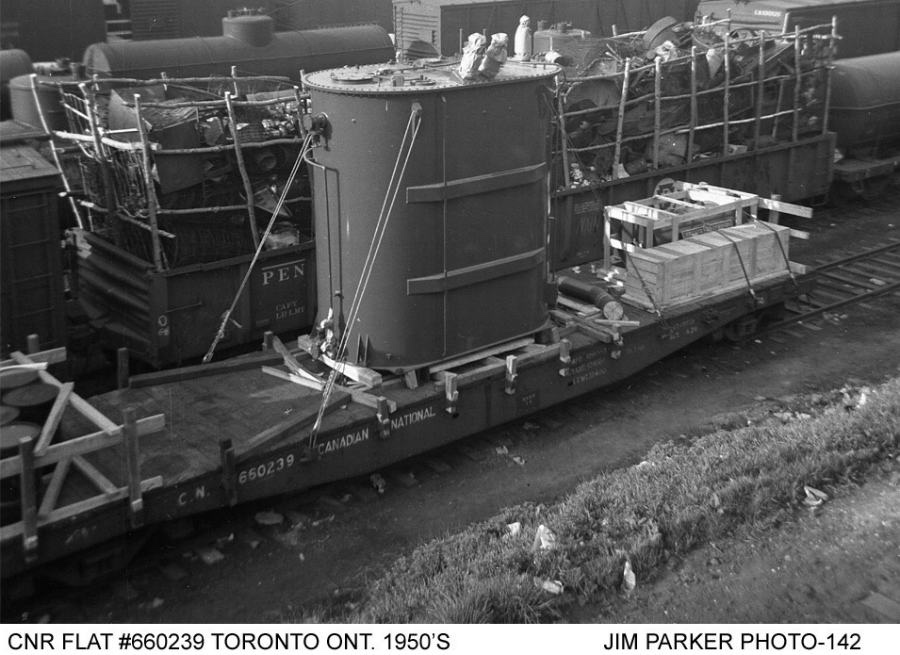
In my last update, I mentioned that my scratch-build of one of CN’s 1929 built “Group C” flat cars was drawing to a close. I am happy to report it is indeed now complete, sans a retainer valve. As I could never discern the valve’s location on the prototype, my thoughts were that it would be better to leave the part off the model entirely rather than guess and find out later it was put in the wrong location.
Let’s begin.
In 1929, CN had 300 46’1″ flat cars built. What makes these 300 cars unique was they were the first flat cars CN had built to its own design. Until this time, all of the flat cars on the CN roster were a hodge-podge of assets inherited from its predecessors, from varying builders and designs.
I learned about these “Group C” cars while working on my CN “A-3” cars: scratch-bashes of two Tichy kits; they are featured in the same two 1994 articles by Stafford Swain in CN Lines (issues V5N3 and V5N4.)
Using the supplied drawings, I cut out a piece of .060″ V-Groove styrene to act as the car floor, and from a sheet of .030″ plain styrene sheet, cut out the side and centre sill plates. The centre sill of the car was then assembled as a sub-assembly, using strip styrene for the bracing, spacing and to simulate the rivet plates. I also added the rivets to the center sill at this point using Archer Fine Transfers, as I knew I wouldn’t be able to get at it after all of the details and side sills were installed.
I took a piece of plain paper, taped it to a piece of glass and then measured out the distance between each stake pocket for the car side sills. I then taped the side sills onto this and glued each Titchy stake pocket to the side sill using the paper as a guide. After the glue had ample time to dry and the styrene had time to properly re-solidify from the solvent glue, I used a #17 blade to take all of the “U bolt” details off the stake pockets. I used the #17 blade to notch a horizontal line across the middle of the face of the stake pocket. Utilizing the notch in the middle of the front of the stake pocket as a guide, I used my flush cutters to cut a roughly 45-degree angle from the center of the face of the stake pocket down to the bottom “foot.” This mimics the prototype more accurately than the Titchy pockets that come from the package. After the stake pockets were completed, I set them aside.
[As you can imagine, the entire process for the stake pockets was an absolute nail-biter because one mistake would render the whole side sill junk… I took a lot of time to make sure I did this cleanly and accurately. I luckily only made one small mistake, which was easily hidden with some Mr. Surfacer 500 painted over the dent in the sill and sanded flat.]
Before installing the centre sill, I drilled out two holes for each truck at a spacing of 35’9″. I then screwed two Titchy Bolsters to the car floor and cemented them in place. Once the cement dried, I fit the scratch-built centre sill snugly between the bolsters, centred it to the car and glued it in place.
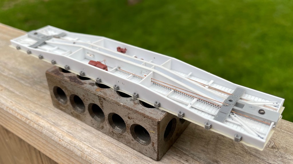
The car mostly assembled, but before the final installation of rivets and decking.
I installed Z-bracing to the car floor parallel to the centre sill. The z-bracing was scratch-built by threading two 1×3″ and one 1×2″ piece of styrene through a homemade jig and glued with Tamiya Ultra Thin. Then I used my JMC Micro Saw to cut out notches to fit in the four more prominent cross members, pre-drilled to accept the train line.
The article didn’t include any photos or drawings of the underframe, so I studied the rivet patterns on the car sides from prototype photos and similarly built flat cars to conclude the location of the cross members and brake components.
The fourteen Z-shaped cross members were installed using leftover z-bracing. I notched out one end of each cross member with a 400 grit PC board file to fit flush against the centre sill. I then ran a sanding block vertically down the side of the car floor to ensure there was no overhang into where the side-sills would be installed.
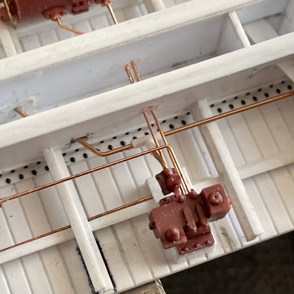
Next, I installed brake levers fabricated from strip styrene into the sill and the Cal-Scale brake parts. This required me to modify the triple valve mount with a file and make hangers for the air tank from phosphor bronze wire.
Before installing the brake piping and rods, I scratch-built a slack adjuster from scrap pieces of styrene and used a Titchy NBW to simulate the bolt into the associated brake lever. The airlines were installed with .010″ wire and the rods with .0125″ respectively. I used Titchy turnbuckles cut in half to act as the clevis on the connections to the brake levers, and scale chain was used between the brake cylinder and associated rod. The last thing I installed on the underframe was the train line, using .015″ wire and a scratch-built “t-valve” from styrene rod, connecting the train line to the triple valve.
Close up shot of some of the under-frame detail, including the t-valve.
While this might seem like a disjointed way to go about building the under-frame of the car, I did it in this order because I knew once I put the car’s body sills on, I wouldn’t have much room to work on the small parts. I had to be careful not to box myself in.
With the under-frame assembled, I next installed the side-sills. To get an excellent 90-degree joint, I used a machinist square on its fat edge to push the sill flush while the glue set. The car ends were installed using 1×12″ scale strip styrene and reinforced from behind with 1×10″ to prevent warping.
The joints were sanded clean, and then corner irons were installed with strip styrene.
I used a single edge razor blade to shave the poling pockets off some spare Titchy boxcar ends I had lying around. I glued the poling pockets on top of the corner irons and purposely used a liberal amount of styrene cement so they would melt into the corner irons to look like one solid part.
With the general shape of the car completed and the underframe more or less entirely assembled, it was now time to install the Smokey Mountain scale coupler pockets.
I measured the centre of the car ends and then cut notches for the width of the draft gear box with my JMC saw. I scored the inside of the car end that was to be removed with a #11 blade and then snapped it out with my tweezers.
This shows the addition to the buffer plate.
The Smokey Mountain coupler pockets were fitted into the car ends, the screw-hole marked with a pencil and then drilled out and installed. As the prototype had a slightly wider buffer block than the Smokey Mountain product, I used a 1×3″ styrene strip on each side of the buffer block on the car end. This also covered up any visible slop between the draft gearbox and the notch cut out for it.
The brake wheel and its mechanism were installed on the car end. I used the Titchy rachet part but decided to upgrade to a brass Precision Scale brake wheel.
The Yarmouth Model Works Carmer Cut Levers were then installed. I used a 4×4″ square of styrene to mount the cut lever, and put a Titchy NBW on top of it to simulate a bolt.
The grab irons were drilled out and installed with .010″ wire, my new go-to over .0125″ as I find .0125″ looks large when painted.
The A-Line stirrups were held over a candle and flattened out straight, re-bent to match the prototype and then installed by first drilling into the bottom of the side sill before being glued in place.
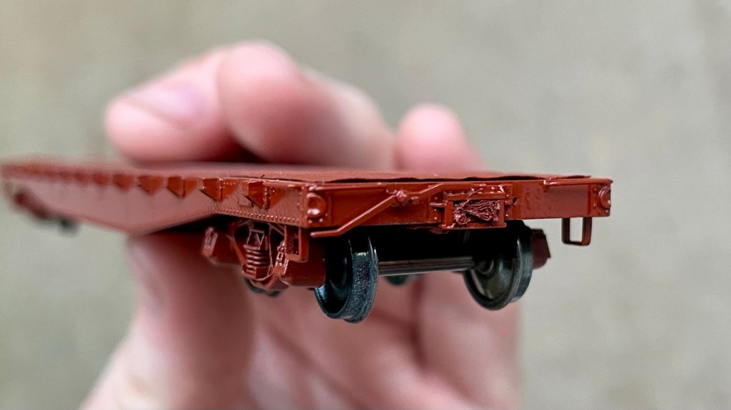
Before painting, I installed all the remaining rivets onto the car using Archer Fine Transfers and the articles drawing as a guide and then installed the Tahoe Model Works Trucks. I also at this point installed the weight into the center sill, which was lead shotgun shot given to my by a friend.
The car was then primed with Tamiya Fine Surface Primer and allowed to dry overnight. I used my regular mix of Vallejo paints to paint the model CNR #11 red. Future floor polish was used to prepare the model for decals.
Black Cat CNR Flat Car decals were applied with the car being lettered for road number #660213, coated again with future floor polish. The car was matte-coated with Vallejo Matt Varnish.
It was then time to install the car’s decking; for this, I used 3×8″ scale lumber from Northeastern Scale Lumber cut into 9′ lengths. I began by first installing a single board on each end of the car, ensuring they were dead centre to the car. After the (15 minute) JB weld had dried overnight, I set a ruler against the boards previously installed on each end and on top of the stake pockets; this created a dead straight line between each back of the car and allowed me to install each board dead center as well. This is an aspect of the build I spent a lot of time thinking out before tacking, as I knew that if the boards waned and weren’t straight, I would not be happy. It turned out to be a straightforward process in the end.
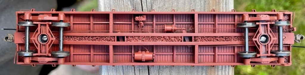
Close up detail of the cars under frame.
Lastly as far as the decking installation was concerned, I drilled out the holes for the end stake-pockets and squared them up with a #11 blade.
With the decking installed, I took a sanding block with 400 grit sandpaper on it. I sanded the deck to level it out a bit and get rid of any fuzzies from the wood I didn’t get before installing. I stained the wood decking on the car with a light mixture of India ink and isopropyl alcohol.
I decided I wanted to try simulating the nails that hold the decking to the car floor. For this, I went to a pharmacy and asked for some of the smallest hypodermic needle tips they had. I measured out where each “line” of nails would be on each end of the car and then used the hypodermic needle against a ruler to install over 400 “nails” into the car deck. I then gave the deck another coat of stain, sanded it, and then stained it one final time. The result is subtle, but I think it turned out well as the nails in a wood deck aren’t that noticeable on the prototype once the deck becomes dirty.
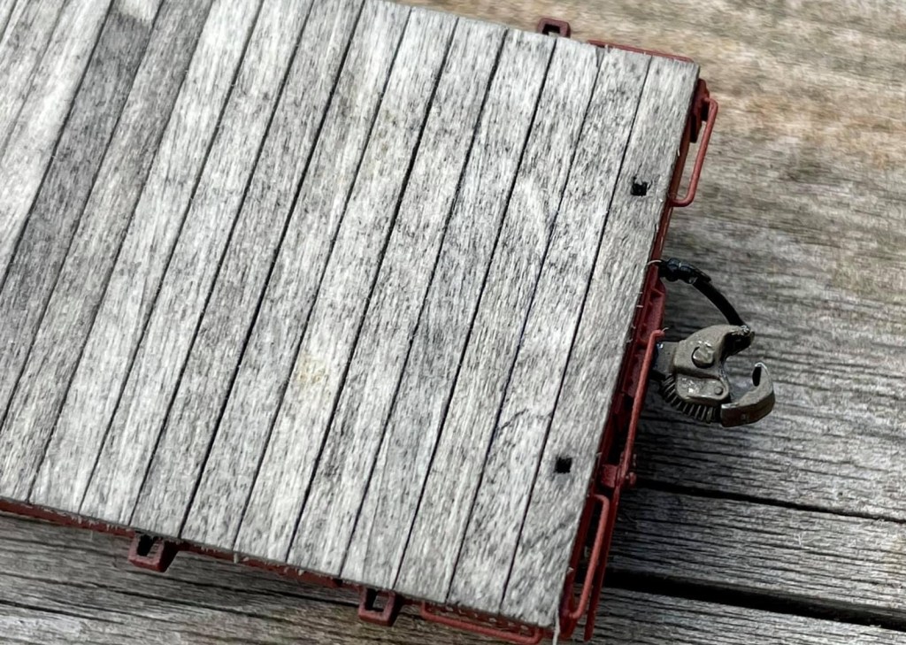
Close-up shot of the completed decking, including the subtle nail details.
Finally, Hi-Tech Details rubber air hoses were installed on each end of the car along with Kadee #158’s.
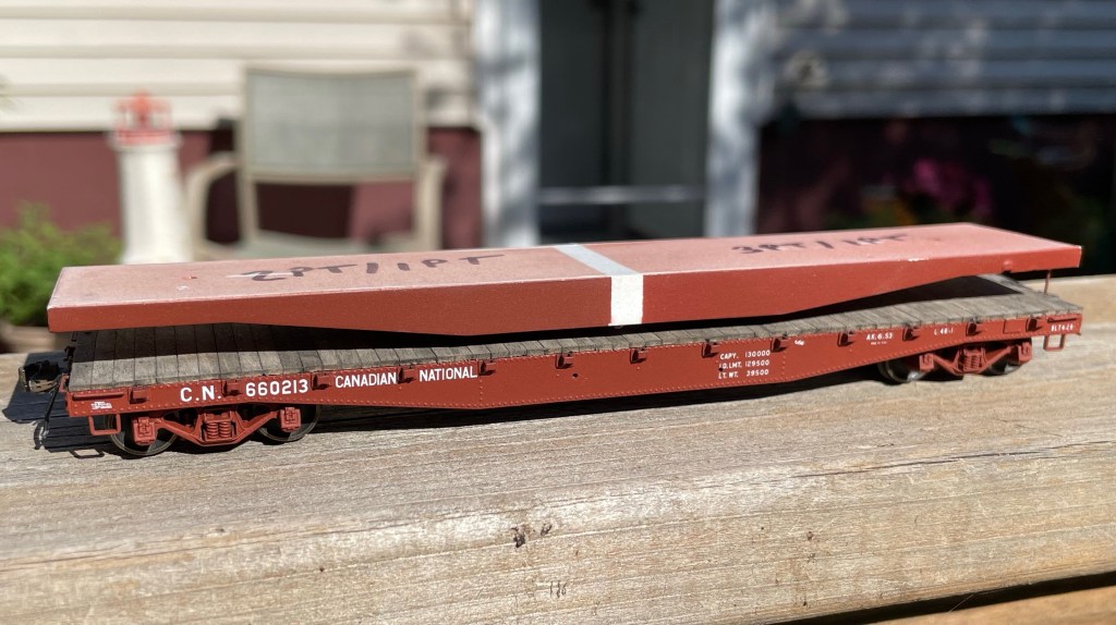
The completed model on the bottom vs the mock-up I made prior to deciding to proceed with the project. The “stripe” in the middle of the mock-up separates two different paint formulas I was testing at the time for #11 red.
That’s a wrap! A long and complicated build is finally completed, and I am very proud of the end result. It is my intent to eventually have this model judged toward an NMRA car-building merit award. Find below a parts and materials list for this build.
Next up, finally more work on that pesky CNR wood-reefer scratch-build (and maybe a new not-so-much scratch built reefer project…..)
CM
RAW MATERIALS:
Evergreen Scale Models:
.060” V-Groove Siding (#14060) [12”x24” sheet, special ordered]
1×2” HO Scale Strip Styrene (#8102)
1×3” HO Scale “ “ (#8103)
1×4” HO Scale “ “ (#8104)
1×6” HO Scale “ “ (#8106)
1×8” HO Scale “ “ (#8108)
1×10” HO Scale “ “ (#8110)
1×12” HO Scale “ “ (#8112)
2×12” HO Scale “ “ (#8212)
4×4” HO Scale “ “ (#8404)
.030” Sheet Styrene (#9030)
.040” “ “ (#9040)
Northeastern Scale Lumber:
3×8” HO Scale Lumber (#3811)
Plastruct:
.010” Styrene Rod (#90850)
Tichy Train Group:
.008” PB Wire (#1100)
.010” “ “ (#1101)
.0125” “ (#1106)
.015” “ “ (#1102)
COMMERCIAL PARTS:
A.A.R. 22” Air Hoses, x2 / Hi-Tech Details (#6038)
AB Brake System, x1 (Plastic) / Cal-Scale (#283)
Barber S-2 50 Ton Trucks / Tahoe Model Works (#113)
The CNRHA (Canadian National Railway Historical Society) and its magazine, “CN Lines,” are undoubtedly well-known entities within Canadian modelling circles.
However, you may not have known that as of July 1st, 2020, you can now purchase a USB drive containing every single back issue of CN Lines for only $50. I sure didn’t, anyway.
That’s right. EVERY. SINGLE. BACK ISSUE on a USB stick for only $50.
This is undoubtedly among the best $50 I have spent in this hobby as a prototype modeller.
The back-issue USB drive paired with the free online index means that I now have over 32 years of accurate and relevant prototype information gathered within the CN Lines Magazine at my fingertips. This has already saved me a substantial amount of research time on my next project, two CNR 40ft flat cars to serve the Vernon River sawmill, which will be Tichy kits modified using a Stafford Swain article.
If you’re looking for a great source of prototype information as a Canadian modeller, look no further and order one of those USB sticks today.
I have no affiliation with CNRHA; I just can’t get over the value!
Small update coming at y’all- and while it’s small, the process behind this was large.
Last night, in the final hours of my 20s, I installed the underslung charcoal heaters and their piping onto Reefer cars’ underframe.
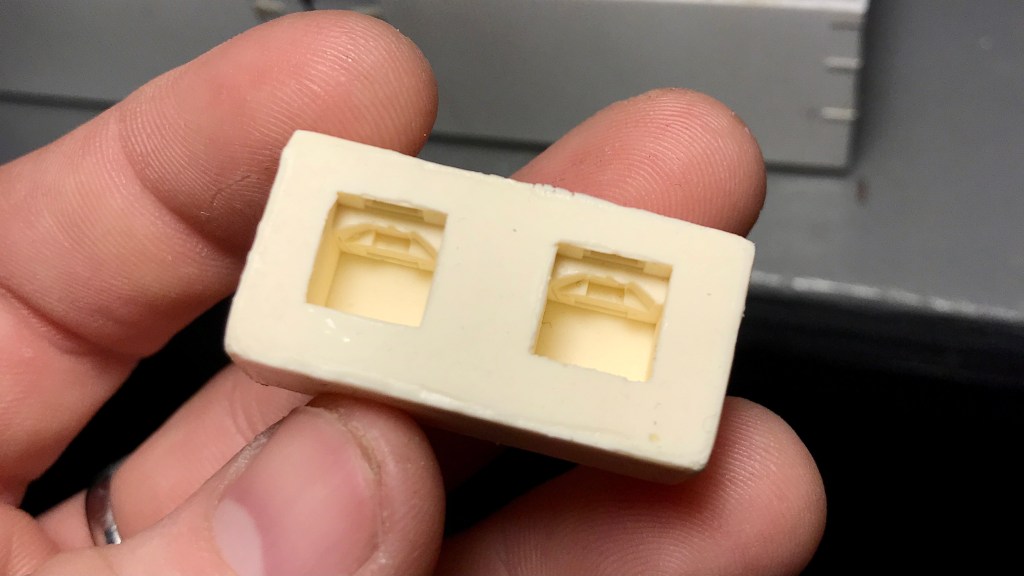
The heaters were resin copies I cast of a certain manufactures underslung charcoal heaters that I could not purchase individually from a kit. I cut a notch out of the previously installed Z-bracing and then affixed the heater right to the car floor with CA.
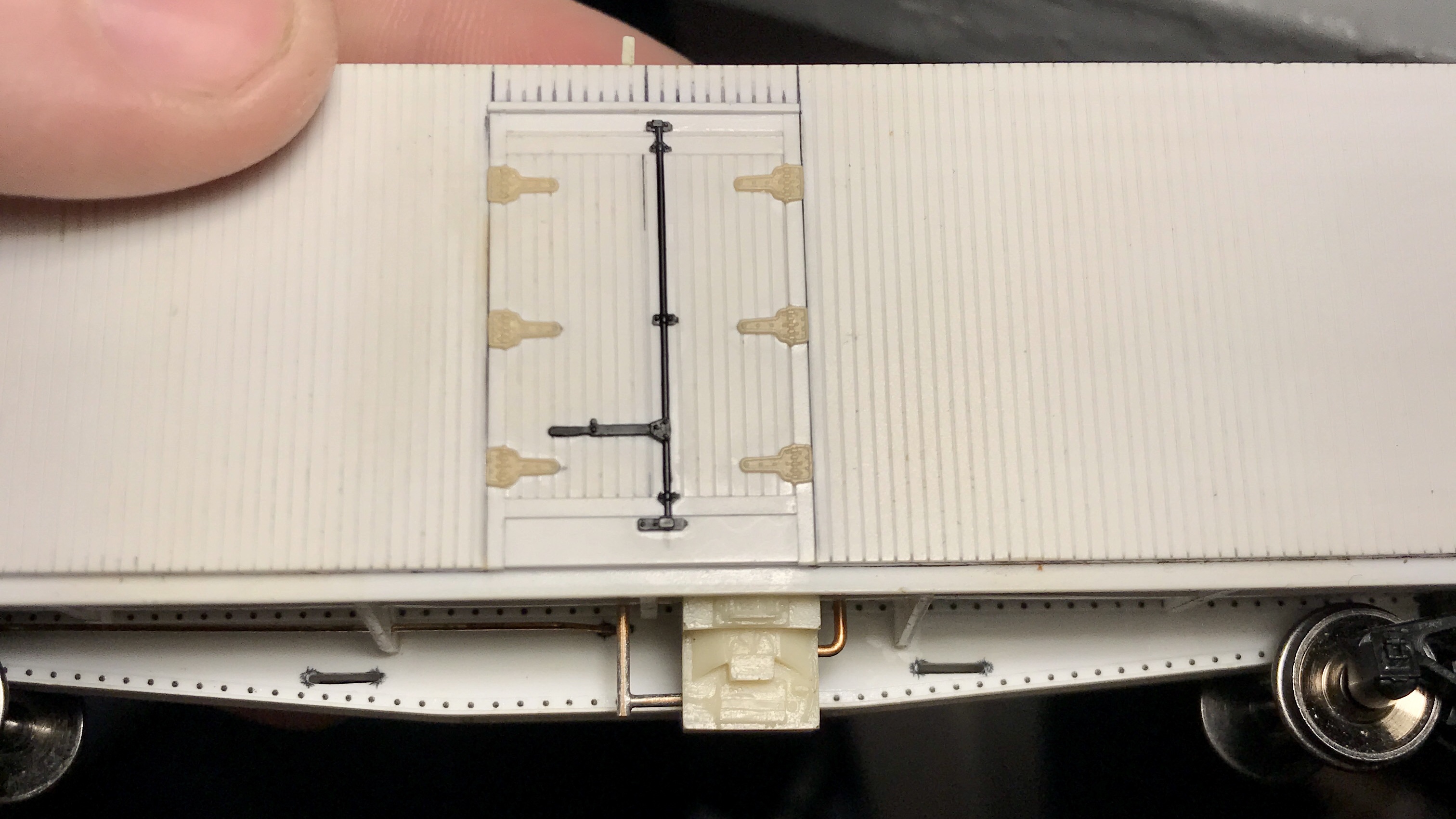
Heater and piping installed on what will become CNR #209232
The piping was .032” Tichy PB Wire threaded through the car floor into small holes drilled into the heaters. I made the “T” joint by first filing the ends of the cut wire totally flat, then used masking tape to hold the wires together in the desired formation on top of some scrap wood. Flux was applied, and solder was liberally applied to the joint. I cleaned it up with 400 grit sandpaper, rubbing alcohol and a wire brush.
The bracing/strapping that holds the heaters to the car floor on the prototype will be installed after the final under-frame installation is made
One of the first things I had to consider before taking on this project (almost a year ago !!!) was the availability of certain parts that would be rather difficult to scratch build- the big concerns being the roof hatches and the underslung heaters.
Well, I was able to find suitable hatches to use (Details West RH-1003). Still, underslung heaters were going to be a different story.
I tried emailing a certain resin kit manufacture multiple times to see if I could purchase some of their cast underslung heaters that they include in their Reefer kits but received no response.
Second, I took to Shapeways to see what I could find. I placed an order with a certain shop for some heaters that looked promising, but when I received them- though they were nice, they just didn’t look as nice as the other manufacturer’s part. And that just couldn’t do.
So, as a last resort, I raided a couple of unbuilt 8 Hatch Reefer kits I have in the closet, got a casting kit at Great Hobbies and cast my own resin copies of the underslung heaters; something I’d never done before.
I’ll spare the casting process, but I’m happy with how they turned out. And while it was a minor headache to not just buy the parts I wanted, this turned out to be a great learning experience, and I’ve learned a new skill.
[A note on ethics: I wouldn’t condone doing something like this (even for personal use only) if the parts in question were still in print and/or readily available. You should always support hobby shops and manufacturers whenever possible. Don’t be a dink.]
Ok. So, before the world exploded my focus in Vernon River land was more or less on preparing for the laying of ties, ballast and track.
For a man who hasn’t even laid flex track before, you could imagine how deep of a daunting rabbit hole this could be.
It has been my full intent since Day 1 with not only this project it’s-self, but my modelling as a whole to hand lay my track. It just seems like the right thing to do and nothing looks exactly like wood, but actual wood.
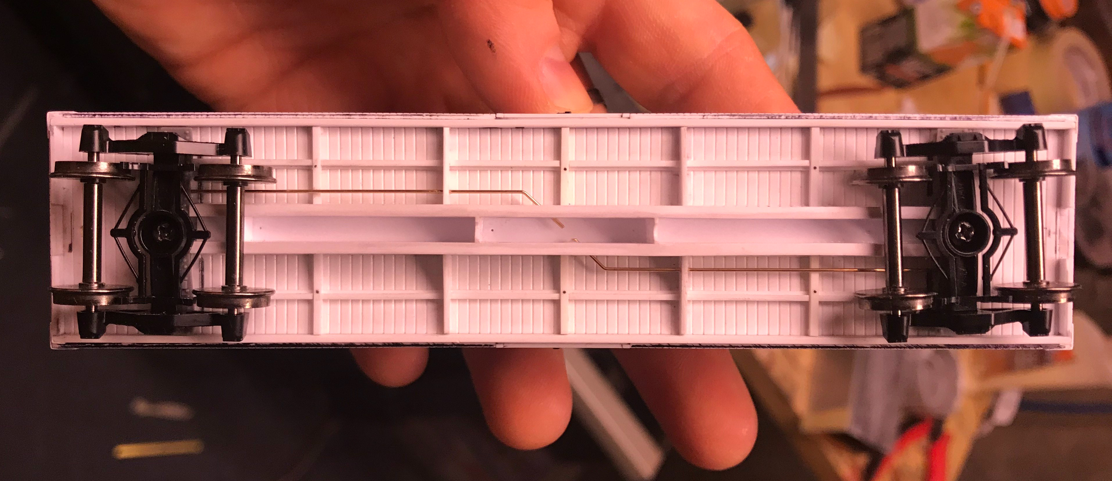
Instead of just going in blind and starting to lay track on my actual bench work I figured it might be fun / a good idea to teach myself this group of skills by building a display / test track.
So that’s what I did.
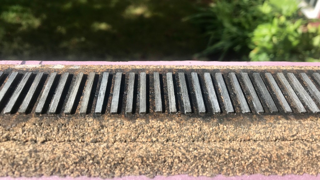
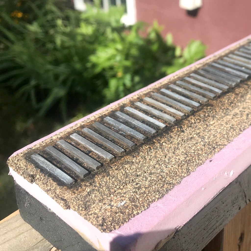
I ordered a “Ultimate Track Sample Starter Pack” with Code 55 rail and 8ft ties from Proto87, snagged a 1×3 that a buddy of mine had from his old deck, got some 1/2in extruded foam left over from a different buddy’s garage build and got to work.
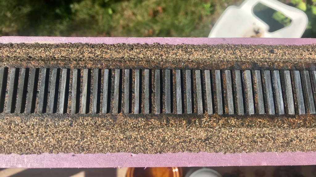
I’ll go over the actual test track it’s self another time. What I want to show off here are my ties.
Hunter Hughson has a great post on Weathering Ties with Acrylic paints over at his blog that I more or less followed to a tee, and man am I ever happy with how they turned out. The only thing I changed from his process was how I went about beating up the ties. Instead of a dental pick, chisel tip and #7 Exacto blades I used a dental pick and wire brush at the suggestion of Chris Mears.
I had the idea to perhaps switch it up and represent a later era with my test track; say the late 70s or early 80s, where tie plates would be more prevalent on the prototype [AKA a excuse to use more of the beautiful Proto87 tie plates that came with the sample pack]. However, I’m leaning back to sticking with the late 50s. I’d still perhaps throw a couple tie-plates down here and there on newer looking ties.
Next up will be ballasting. If I stay with the late 50s it’ll be cinders, if I go with the late 70s / early 80s it’ll be a mix of crushed rock.
Well, it’s been longer than I would have liked between updates.
This whole COVID-19 mess has certainly affected every one of us, and us in the aviation industry, especially in terms of employment. My employer has placed myself and roughly 15,000 other of my union brothers and sisters on off duty status, which has admittedly been hard to comprehend given how quickly all of this has erupted.
Without getting too personal, I’ll just say this whole mess really hasn’t left me with much motivation to write. However, as the dust of our new reality begins to settle, I’m starting to feel a little better. That said, this post isn’t nearly as beefy as I’d like it to be, and I must apologize.
Progress has continued on the reefers, and I’m really starting to get excited about where this project is headed. The fishbelly sills have been riveted with MicroMark surface decals and installed along with the z-bracing, cross-bearers, cross-members and train line.
After installing the z-bracing (which I put on the wrong way somehow! whoops!), I used my UMM saw to cut through the bracing and installed the cross braces and cross members. I went with 4×4″ Evergreen for the cross members and used my Cricut Maker to cut the cross bearers from .030″ Evergreen sheet. The cross bearers will receive a 1×6″ cap over them after the floor is glued into the cars.
With the sill, z-bracing and supports installed I figured now would probably be a good time to install the tramline as it needs to be threaded through the cross-bearers. I bent .020″ Tichy PB wire directly over top of the scaled down general arrangement drawings, cut it into two pieces and installed it into the car with CA. This was repeated for both cars.
Another view of the under frame.
Next time, I intend to make a drill jig for the side and end grab irons using the engraving tip on my Cricut Maker. I plan to design the jig in 2D with CAD, engrave it onto a .010″ brass sheet (or a soda can), cut it out, fold it against a vice and then use my pin vice to punch the holes before using it to drill out for the grabs.
We’re all facing a lot of stress right now… I encourage you to take some time and work on or run your models. We all need to get our minds off of things. Please wash your hands and stay home.
Telling the stories of the history of the port of Charlottetown and the marine heritage of Northumberland Strait on Canada's East Coast. Winner of the Heritage Award from the PEI Museum and Heritage Foundation and a Heritage Preservation Award from the City of Charlottetown