CNR CLC H12-44 #1639 in 1:87: Part 1 — Reverse Engineering in 2022

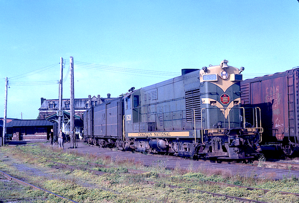
The prototype: CLC H12-44 CN #1639 at Charlottetown, PE – 29JUL1961
Photo by: J.W. Vingrass / Krambles-Peterson archive (www.thedieselshop.us)

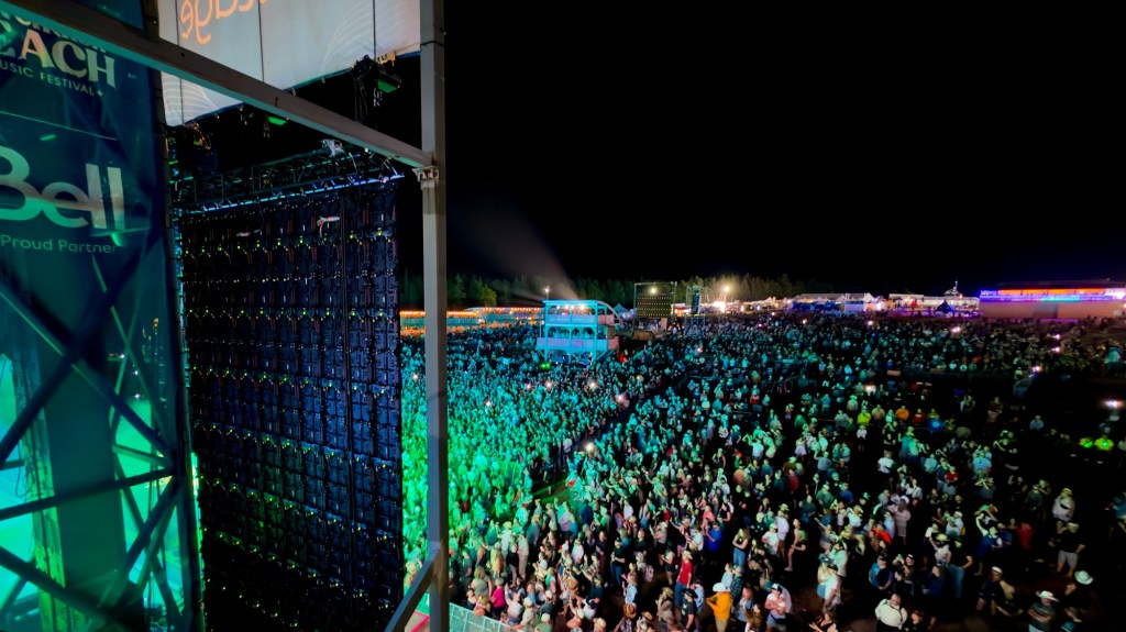
You know, before we get into it, it’s kind of funny. I just got home from being back-stage at a concert with approximately 15,000 people in attendance, and most of the time I was there I was thinking about writing this post and how to execute the next phase of this build. While my old life does creep back into the picture from time to time, we’re about ten years deep into the train-bug. I think it grabs harder somehow.

Here’s a picture of that, for fun:
Ok, train stuff.

Back in 2022, I became drawn to a H10-44 to H12-44 conversion project I found in Steve Hunter’s files. Like how most good projects start, I saw something shiny and couldn’t stay away from it. Steve had gone to great lengths to begin converting a Walthers H10-44 into a proper Canadian Locomotive Company H12-44, and I was captivated not only by the thought and planning he had put into getting the project off the ground, but by how monolithic, heavy-looking, and frankly cool the #1630–1639 series CLC locomotives were. Steve had well-documented his progress in photos, as well as in various places around the internet. Unfortunately, the only remaining online source I can still find appears to be on The Diesel Detailer forum, which I have linked to before and will link here again.

CLC H12-44 CN #1637, as built.
(Ingenium Archives, CN Images of Canada Collection, X-46343 : http://collection.ingenium.ca/en/id/X-46343/)

Built by the Canadian Locomotive Company of Kingston, Ontario, under licence from Fairbanks-Morse, CN’s H12-44s were delivered in two groups: #1630–1639 between AUG and OCT1955, followed by #1640–1659 between APR and JUN1956. As built the #1630–#1639 series, the subject of this project, had a steam-era-style body-mounted handrail arrangement (similar to a boiler rail), and side handrails were later added by CN. The later #1640–#1659 series came from the factory without the body handrail, proper side handrails, a wider hood, and longer battery boxes, among other differences. The subject of this build, #1639, came from the first group and is the most often seen CLC PEI unit in my photo stash, hence it’s been chosen as the prototype.

Soon after getting hooked onto the idea, I found a cheap Walthers H10-44 of my own at a train show and began to tinker. The tinkering quickly snowballed into a full reverse-engineering exercise, as I worked to figure out the process Steve had used to modify the shell, extend the body to the correct length, extend the hood end, and correct the profile of the front of the hood. Much of the reverse engineering was achieved by converting Steve’s progress photos to scale, the main culprit being a scanned side-profile image of the actual in-progress model post surgery. Scaled down, it lined up nicely and could be compared against the drawings in CN Engineering’s Diesel Data Book.
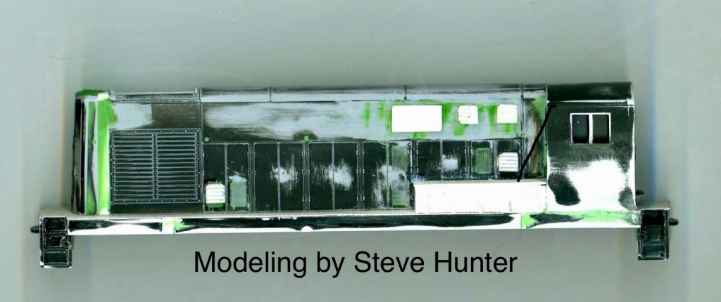
The side-profile scan of Steve’s build in progress, which allowed me to scale it down to 1:87 and compare it with the general arrangement drawings from CN Engineering’s Diesel Data books. Of course, some trust in the originally modeller is needed when scaling down their work, but I have no doubts that he got it right.

While it has been over four years since I last worked on this project (!!!), I really do believe it deserves to be finished before starting anything else, IE: the RSC-13s. And I want to be clear: I am absolutely copying Steve’s build while adding my own flavour to it, and it is absolutely out of homage to one of the greats of PEIR scale modelling. Steve absolutely loved sharing his modelling and knowledge of the PEIR with anybody who was interested. I have no doubt he’d be happy that his work is being shown, and expanded upon. Another aside, I actually have no real need for this model LOL, as CN’s H12-44s were primarily used on the “Boat Train” between Charlottetown and Borden, PEI, which is not a stretch of railway I have intentions of modelling, either past or present. Still, sometimes a prototype grabs you anyway. It’s just cool.

To the nitty gritty:

It has been long enough that I don’t remember the exact order in which I worked, but this is the mostly complete list, as of now, of what was completed before shelving the build.

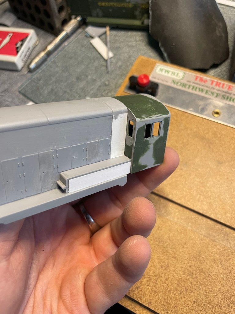
  • The original Walthers shell had a lot of details that were not present on the CLC units, including Fairbanks-Morse-style fairing on the cab end and skirting above and over the battery boxes. These were among the first details I removed.
  • All louvers on the hoods doors were filled with Mr. Surfacer 500 grit primer and removed.
  • All of the molded door handles were chiselled off and replaced with handles made from phosphor bronze wire.
  • All molded window gaskets were removed. These may be left as-is, or replaced using the Andrew Castle method: gluing .005” styrene sheet over the window openings, then cutting and filing it back until only new, more scale-accurate gaskets remain around the edge of the window.
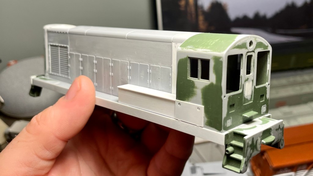
  • The Walthers model featured four windows on the rear of the cab, along with an extra window in the cab door. The four rear windows were converted into two larger windows to match the CLC prototype, and the extra window in the door was filled with styrene and removed.
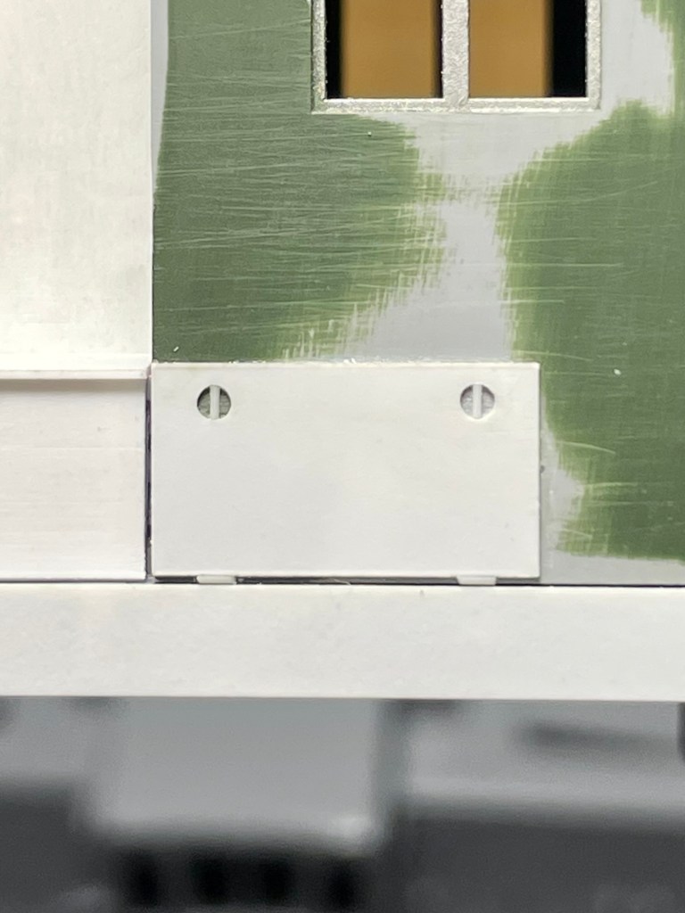
  • New access doors were added to the sides of the cab, with .010” styrene rod set into drilled holes to represent the prototype’s round latches.
  • KV Models Sunshades were installed.
  • Holes were drilled for wind deflectors, also by KV Models.
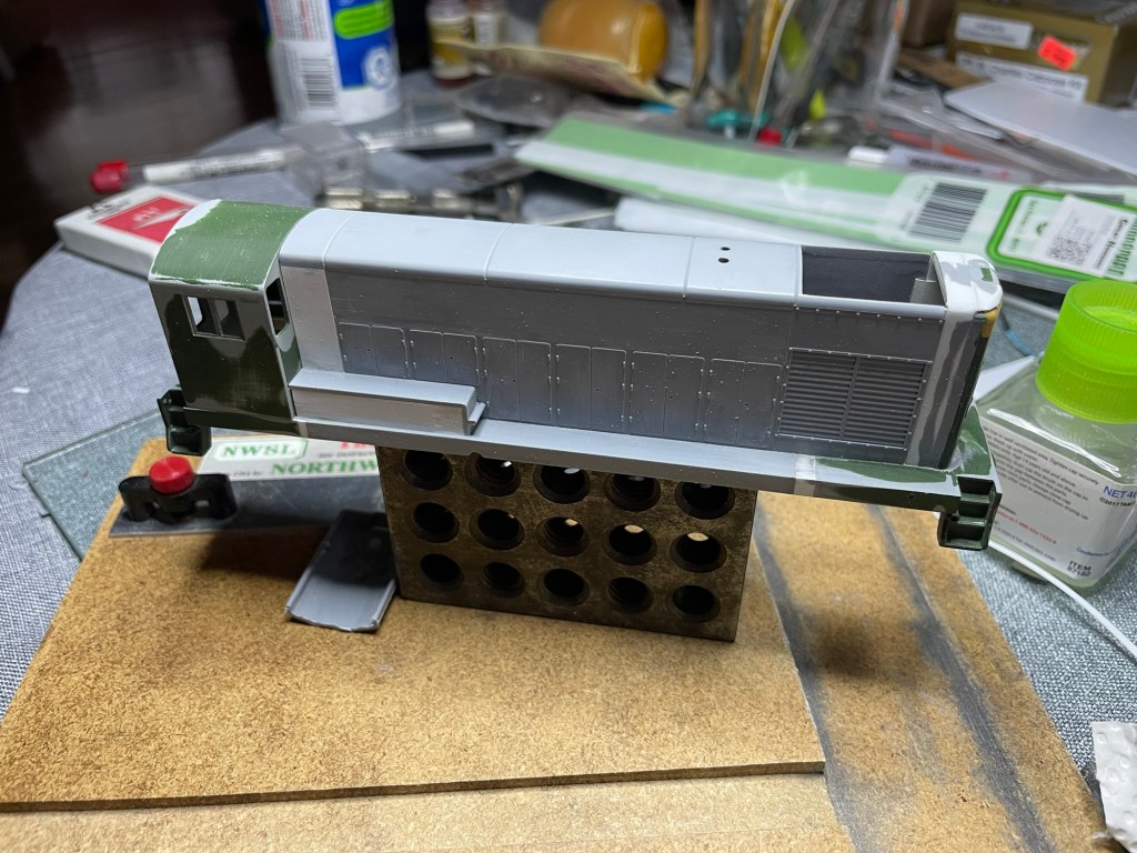
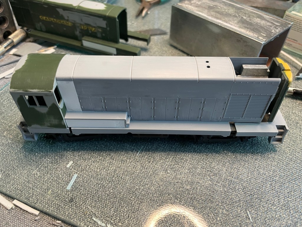
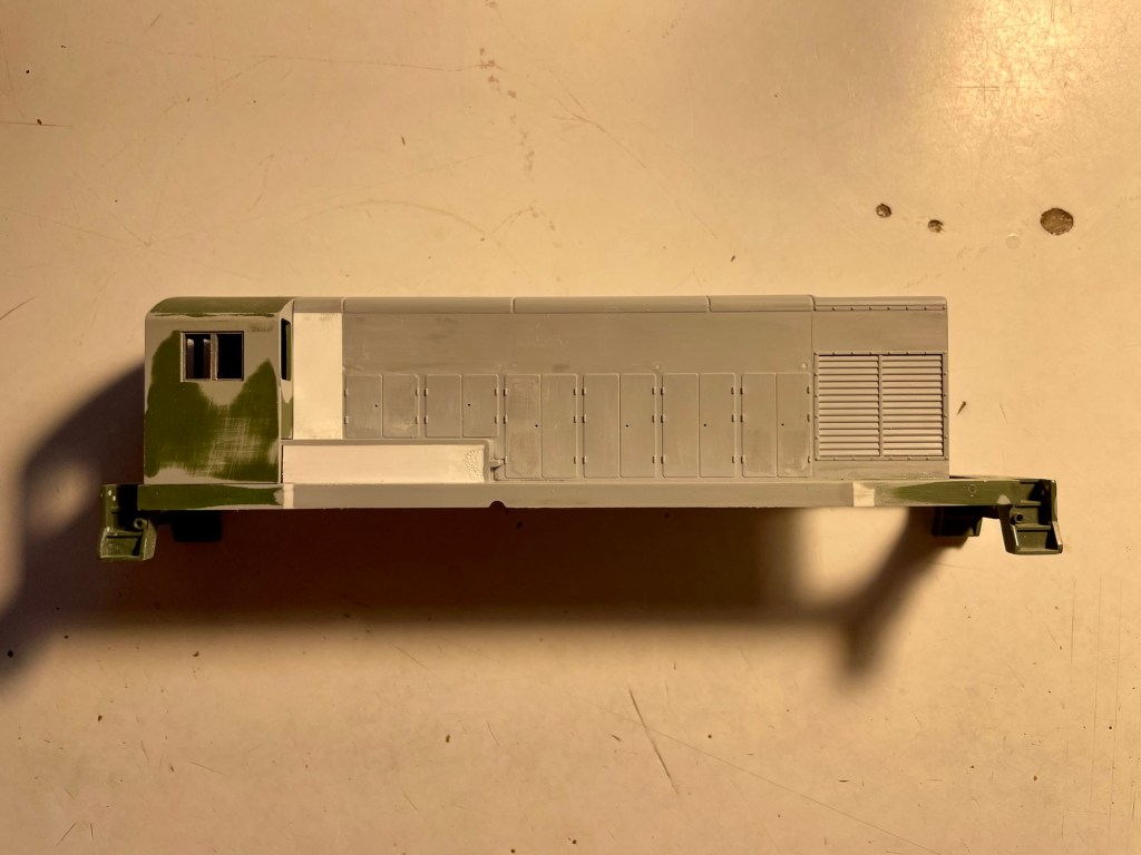
  • The body was extended by cutting the shell in two separate places and adding styrene: once at the radiator section, and again just ahead of the cab.
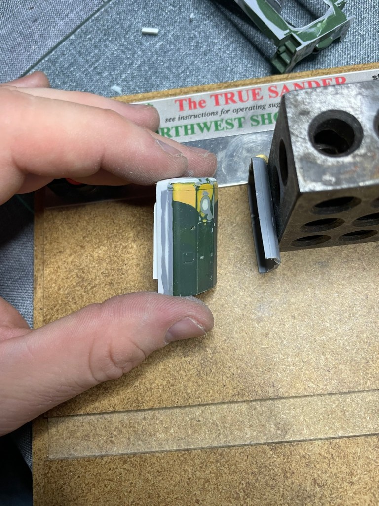
  • Since the longer body also required a longer hood, the nose of the locomotive was cut off and extended with styrene. The rear of the nose was sanded flat to remove the original angle, then reattached vertically to the extended hood.
  • Certain areas of the body closest to the cab were filled in with .005” sheet styrene to match the CLC prototype.
  • A thin strip of styrene was added over the side sills to cover any remaining evidence of the body surgery, while also matching the prototype. This will also allow the “CANADIAN NATIONAL” decal to sit properly along it.
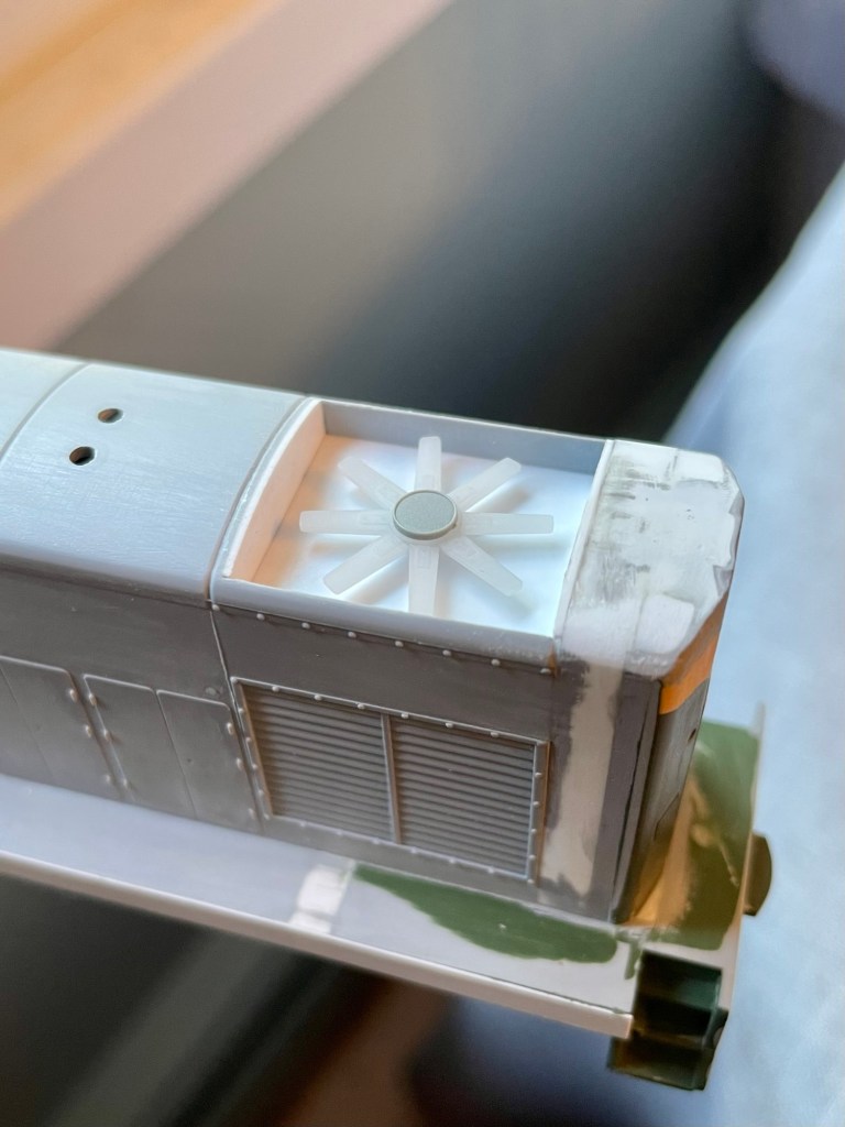
  • The molded plastic roof grille, which was frankly terrible, was cut out, and a styrene box was built inside the shell. That box now houses a proper fan and will eventually be covered with a scale grille.
  • The molded exhaust stacks were chiselled off, the area was sanded clean, and holes were drilled to eventually accept hollow brass tubing for more accurate exhaust stacks.
  • Accurate battery boxes were scratchbuilt over the remains of the original FM ones to better match the CLC prototype.
  • Access hatches were added to each upper side of the body, which will eventually receive louvers to match the CLC prototype.

And of course, here are various photo’s of the build, with the top one being the most recent. The rest were taken years ago!
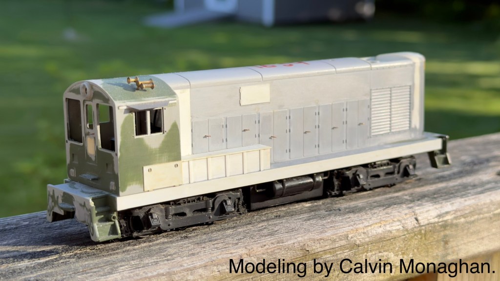
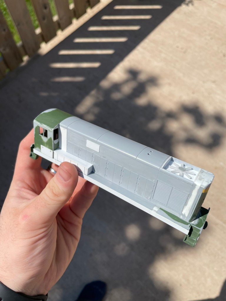
While there is undoubtedly a lot of work left to be done, I do feel the model was shelved at a good juncture to pick it back up again. All of the major body surgery is done, the incorrect details are gone, and from here it becomes a more straightforward exercise in detailing the locomotive. The remaining major exception to that will be the side railings, which appear to have been added sometime between the #1630–#1639 units being built and their arrival on PEI, presumably for safety reasons. Other big decisions will be regarding louvers (to scratch-build them, or use Archer louver decals, which will be to small) and to or not to scratch-build a new frame from brass. If you have any experience or suggestions in regard to scratch-building louvers, drop me a line!

All of that aside, when I pick this up again, hopefully soon, the next goal is to knock out the grab irons that are just forward of the radiator, and then the body-mounted handrails. The rest will sort itself out.

Thanks for reading. That’s two in one month if you’re counting!

CM/YYG
The Best $50 You Can Spend In Canadian Prototype Model Railroading.

The CNRHA (Canadian National Railway Historical Society) and its magazine, “CN Lines,” are undoubtedly well-known entities within Canadian modelling circles.

However, you may not have known that as of July 1st, 2020, you can now purchase a USB drive containing every single back issue of CN Lines for only $50. I sure didn’t, anyway.

That’s right. EVERY. SINGLE. BACK ISSUE on a USB stick for only $50.

This is undoubtedly among the best $50 I have spent in this hobby as a prototype modeller.

The back-issue USB drive paired with the free online index means that I now have over 32 years of accurate and relevant prototype information gathered within the CN Lines Magazine at my fingertips. This has already saved me a substantial amount of research time on my next project, two CNR 40ft flat cars to serve the Vernon River sawmill, which will be Tichy kits modified using a Stafford Swain article.

If you’re looking for a great source of prototype information as a Canadian modeller, look no further and order one of those USB sticks today.

I have no affiliation with CNRHA; I just can’t get over the value!

– CM

PEIRwiki.ca

Well, to put it simply: the time has come.

The time has come for the PEIR (Prince Edward Island Railway) to have its own collaborative, indexed, searchable and accessible corner of the internet.

After a few years of on and off thought and consideration, and after seeing one previous attempt: I have taken it upon myself to follow in Steve Meredith’s footsteps (DARdpi.ca / DARwiki) and start a PEI Railway wiki website entitled the “PEIRwiki.”

With the PEIR, I’ve always found that while there is a vast amount of information out there, it’s all quite scattered. When I was new to the interest of railroading, I found this scattering of information daunting.

I want to change that.

I want anybody with even a passing interest in this railway to access detailed, accurate information. I also suspect this will augment my own research in the railway.

So with that said, I present to the world PEIRwiki.ca.

Anybody who is interested in or knows somebody who would be interested in contributing, please get in touch.

I dedicate this effort to Steve Hunter.

C.M.

Finding inspiration from a later era

IMG_1253.JPG

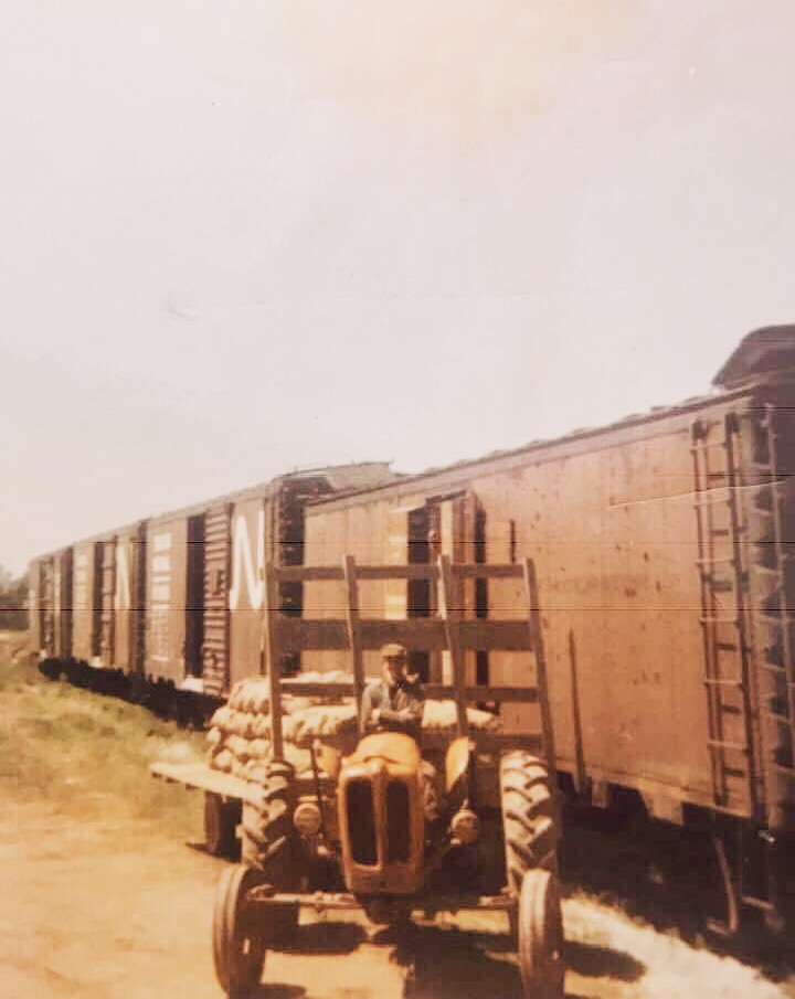
Loading potatoes at St. Peters Bay, PE – Late 60s 1970s? Jim MacKinnon collection.

While looking for photos of tractors on The Prince Edward Island Railway Facebook page, I came across this photo of a reefer being loaded with potatoes at St. Peters Bay.

The author of the post incorrectly labelled it as the 1950s, but as we know by the noodles on the boxcars, this is post-1961. Further, the American reefer car’s presence makes me believe it might even be the late 60s or 1970s.

While this photo isn’t within my era, it really strikes some inspiration. The railway on PEI had many public sidings or team tracks- but not many of them had permanent loading ramps. The public siding at Vernon River did not have a loading ramp.

This scene might as well be Vernon River. It would be a very similar scene. The farmer or merchant backs truck or trailer right up to the car, plywood ramp bridges the gap, potatoes are transferred across- probably a lot of the time “hand-bombed

.”

I am very grateful to find this picture. It will be used as a direct reference to develop the scene and the public siding.

As mentioned at the beginning of this post, I’ve in passing begun to research era-appropriate vehicles for the layout. My first purchase was an Alloy Forms 1947 Clark Forklift, which will live at the Co-Op Warehouse… I just need to figure out the proper colour to paint it.

I’ve mentioned this before to friends, and you may disagree, which is fine. Still, I really find that too many vehicles are the easiest way to break a layout’s realism. Luckily for my era, Route #3 wouldn’t have been nearly as busy as it is today, hell it probably hadn’t even been paved to long before- there won’t be any vehicles on it, and that won’t look out of place. I’m thinking a car or two parked at the station, a truck parked at the warehouse, a tractor and potato trailer along the siding and maybe an abandoned truck in the corner of a farmer’s field will be sufficient.

CM

Vernon River Co-Op Warehouse: a study on shared building plans.

IMG_1210

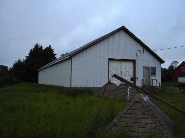
The former Vernon River Co-Op Warehouse built in 1947. July 2013. Chris Mears photo, used with permission.

Since the very conception of this layout, a mystery has been at the back of my mind. That is the mystery of the Vernon River Co-Op Warehouse.

Perhaps not as much of a mystery as a minor annoyance. You see, the photos I have are only but a tease only providing partial views of how this building looked while it was still rail-served.

There is one fact working for me: the building still stands today- rails to trails use it as a workshop. Having an accurately sized model will not be a problem; however, its freight doors and roof vents have been removed, and the roof and siding have been replaced.

I’ve reached out to local area Facebook groups to find a better photo of the building with its freight doors still intact, to no avail. I’ve reached out to the archivist at St. F.X. University, which does have a giant photo collection of Co-Op buildings, PEI included- to no avail. (One avenue I have not yet explored is to contact rails to trails and see if I could be allowed inside to see if the door framing is still visible.)

This information gap has mostly left me to fill in the blanks myself.

However, just this morning, I had a bit of an “ah-ha” moment.

I don’t know why this didn’t hit me before now, but I had already been aware of direct evidence that the co-operatives routinely shared building plans, being co-operatives and all. One such example is the Co-Op Potato Warehouses at Morell, Tignish and Souris being nearly identical.

Could the Vernon River Co-Op warehouse be a shortened version of these other warehouses?

IMG_1199

Morell’s Co-Op Warehouse. Year and photographer are unknown. St. F.X. University Archives.

20935076_1902309463423996_4088096629602011681_o.jpg

Souris Co-op Warehouse. Steve Hunter photo, year unknown.

IMG_1209 copy

Tignish’s Co-Op Warehouse. Year and photographer are unknown. Note that the building is nearly identical to Morell’s warehouse, a county away.

What caught my attention is how similar the front of the Morell warehouse looks to the front of the Vernon River warehouse. The large double door and loft door are of identical construction. The chimneys are similar. While in different locations, the man-door and window are of very similar structure. What we can see of the first freight door shows us that these doors are also very similar, if not identical, to the Morell warehouse.

To corroborate my theory, I took to Google Earth and went back in time to 2015, when the Morell warehouse still stood. Now, the two warehouses’ lengths obviously differ- we don’t need Google to tell us that, but I was most interested in finding out if the buildings were the same width.

I’ll be the first to tell you that Google Earth’s measurements aren’t always so accurate (they even admit this themselves). Still, I figured that if I measured the buildings from a satellite image taken on the same day, I’d be able to figure out if they were the same size.

What I came out with was this:
Morell warehouse= 43.24′ x 122.82′
Vernon River warehouse = 44.91′ x 82′

Given Google’s inaccuracies and satellite imaging variables, the widths are very close indeed. I’ll take that as a win.

So now we know that the Vernon River and Morell warehouses were, in all likelihood, the same width. The similar width dimension, look, owner, and use of the building make me feel comfortable using the Morell and Souris photos as a reference for the Vernon River build. The Morell and Souris photos, along with a scale drawing of the Morell warehouse Steve Hunter gave to me, will most certainly get me most of the way there.

Without a photo showing the Vernon River warehouse’s entire side, we don’t know how far apart the two freight doors were.

I can figure this out in two ways:
– Obtain permission to enter the warehouse as it stands today and see if the door framing is still visible from the inside.
– Measure the outside of the warehouse and use the 1958 air photo to scale out the door centres.
These methods will have to wait until the snow melts, but I’m happy having figured out the process I’ll have to follow.

One final question I may never have a firm answer on involves the relationship between the truck door and the foundation.

In the Souris, Tignish and Morell photos, the land is built up to the top of the foundation to meet the truck door- meaning the truck door doesn’t go through the foundation. However, in the Vernon River photos, it appears as if the foundation has been cut to allow for a taller truck door. The man door placement above the foundation caught my suspicion and made me believe that the ground was initially built-up like the other warehouses. For some reason, the door’s height needed to be increased, so the foundation was cut to allow for this.

As you can see in the 1981 Vernon River photo, it looks as if a whole new door frame has recently been installed and the earth around the foundation excavated. The man door remains above the foundation. Perhaps this is all the evidence I need.

After studying the images, I have concluded that it’s very likely that at some point, the foundation was cut to accommodate a taller truck door- most likely in the early 80s. Wouldn’t the man door be cut into the foundation if the building was initially built like this? I feel confident I can model the door as shown in the Morell photo, with it being accurate.

Unfortunately, I’ll have to wait until the spring to further this research as it requires a field visit. Still, I feel confident that I have most of the information I’ll need to scratch-build this building.

If you’ve stuck with me this long, thanks for reading.

CM

A sunny winter’s day prototype visit.

After Wednesday’s hangout with Taylor, Chris and David I was feeling pretty pumped about the direction of things.

That feeling was only amplified after a Saturday afternoon spent in New Brunswick operating on Doug Devine’s Island Central Railway and Steve McMullin’s Carelton railway.

Even though we we’re very much in the dead of winter here on Prince Edward Island, spring was definitely in the air this Sunday afternoon. I couldn’t resist making the first of what is likely to be many visits to the prototype location.

I can look at photos all day but to catch onto the feeling of the layout I really needed to get out to Vernon River its self and get an idea of how the land lays in 1:1.

Instead of photos, I thought it would be easier to just make a short video which you can find right here:


I will return when the snow melts and again in the summer. I plan to take many photos of the right of way,  trees, buildings, farmers fields and farm roads in the area to get a good idea of how I’ll model them.

C.M.

Vernon River / Murray Harbour Subdivision traffic analysis [PT:2 Researching Traffic Amounts and Crunching the Numbers]

7751 on Murray Harbour Sub CN002589
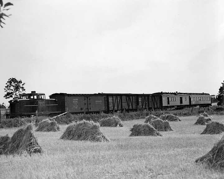
44 Tonner #7751 leads a mixed train on the Murray Harbour Subdivision. #7751 was renumbered #2 June 1956. Photographer unknown. CSTM Collection (#CN002589)

In my previous post I used newspaper archives to determine and describe the types of traffic I thought Vernon River would normally see.

My goal is now to not only determine the amount of freight traffic Vernon River would see but to also determine the average train length, loads and percentage of originating vs terminating traffic on the Murray Harbor subdivision as a whole. Having these statistics will allow me to accurately model the car movement both through and at Vernon River.

This info is important for a few reasons, but mainly I need to be able to:

  • Determine in general terms the amount of switching moves per operating session
  • Determine to the average train length through Vernon River
  • Determine the usual ratio of originating to terminating cars
  • Use the above information to figure out how long the single track staging cassette will need to be on each side of the layout.

With the new Drive-By Truckers record on in the background, into the rabbit hole I went.

In my files I found a summary written by Shawn Naylor of a freight report CN completed in the early 1960s. Apparently this report was prepared to propose reductions in PEI’s rail service. In the report CN used carload data from the mid to late 1950s which makes it super conveniently accurate for my layout’s era.

Below I’ve created a spreadsheet of carload data as it applies to the Lake Verde, Vernon [Loop] and Murray Harbor subdivisions from this summary (the same mixed train #240N / #209S served these subdivisions.)

1958 Daily Carload Data: Lake Verde, Vernon [Loop], Murray Harbor Subdivisions

STATION

ORIGINATING CARLOAD / DAY

TERMINATING CARLOAD / DAY

TOTAL

Millview0.4NIL0.4
Vernon [Loop]0.51.01.5
Murray Harbor0.10.10.2
Mount Albion0.6NIL0.6
Other Lake Verde, Vernon and
Murray Harbor 
Subdivision Stations
2.00.72.7
TOTAL3.61.85.4
If you’re not familiar with island railroading it’s important to note that “Vernon” and “Vernon River” are two different locations. I’ve marked Vernon with [Loop] to make it less confusing.

Using the numbers on the chart it would be fair to say the average train could include around five freight cars- a pretty low key operation. Most photos I’ve seen reinforce this, showing on average zero – three freight cars plus the baggage and coach car. [With a train so small I should be able to get away with a 5ft staging cassette on each side of the layout]. Obviously not all of these cars would be destined for Vernon River. In fact, it probably wasn’t a daily occurrence that anything would even be switched there. For the sake of fun, my layout will only operate on days where there is an originating or terminating load for Vernon River.

Knowing the average train length I now need to know what types of freight we’d see on that train. Naylor’s summary includes traffic types for the Murray Harbor, Lake Verde and Vernon [Loop] subdivisions but the figures are irrevocably lumped together with the Montague and Georgetown subdivisons. I can live with that though- the Montague and Georgetown subdivisions would have seen pretty similar types of traffic. It shouldn’t distort our reality too much.

1958 Originating vs Terminating Carloads: Murray Harbor, Vernon [Loop] & Lake Verde Subdivisions:

  • Originating Carloads: 67%
  • Terminating Carloads: 33%

1958 Originating Carloads: Murray Harbor, Vernon [Loop], Lake Verde, Montague and Georgetown Subdivisions:

  • Potatoes: 57%
  • Turnips: 33%
  • Other: 9%
  • Livestock: 1% (Aprox 13 carloads per year)

1958 Terminating Carloads: Murray Harbor, Vernon [Loop], Lake Verde, Montague and Georgetown Subdivisions:

  • Other: 54%
  • Sand and Gravel: 27%
  • Fertilizer: 13%
  • Coal and Coke: 3% (Aprox 30 carloads per year)
  • Animal Feed: 2% (Aprox 27 carloads per year)
  • Petrol Products: 1% (Aprox 9 carloads per year)

In Naylor’s summary is it said that a contributing factor to PEI’s high operating costs was the need to use different cars for originating and terminating traffic; cars used to import things to the Island tended to leave empty. As such, local moves will range from very rare to non-existent on this layout.

With these statistics I now have a great foundation to base my layouts operations around. Even though I’m only modelling a single village, I think its important to consider the subdivision as a whole in order to serve my chosen village accurately. 

Now I just need to figure out how to work these averages and percentages into a car card system…

CM


Vernon River / Murray Harbor subdivision freight traffic analysis [PT. 1 Researching Traffic Types]

With a prototype chosen it was time to dive a little further into my research.

My first goal was to figure out the types of freight traffic the village would see in a broad sense and not just my chosen era; after having that information I could then, through logic and evidence, figure out what would be applicable to my era.

One of the primary tools for the research job was islandnewspapers.ca. – “a fully-searchable online archive of PEI’s main newspaper of record, The Guardian, from 1890 to 1957.” This archive along with a document by Shawn Naylor that Steve Hunter passed to me a few years ago provided me with a wealth of information.

What I found was that Vernon River received quite a few different commodities ranging from general merchandise to mussel mud. Its main exports would have been produce (potatoes likely being the majority of this) and livestock (mainly hogs). 

I have compiled the following list of inbound and outbound traffic. Everything listed is based upon direct evidence (unless marked with a “*” or “**”) found in newspaper archives or in Naylor’s document. 

  • Outbound Traffic:
    • Produce (Potatoes, Turnips and other crops)
    • Livestock (mainly hogs but also cattle)
    • Finished Wood (*) (not likely in my era)
  • Inbound Traffic:
    • Animal Feed
    • Limestone
    • Fertilizer
    • Bulk Oats
    • Barley
    • Bulk Wheat
    • Fuel (**) (would oil and gasoline be pumped from tank cars into trucks to supply farmers with fuel?)
    • Coal (OCS and revenue)
    • Ties (OCS)
    • Mussel Mud (not likely in my era)

(*) Outbound loads of finished wood is a assumption at this point and only that. This is based on the existence of a saw mill about half a km away from the station. While I have not found any evidence to back up this assumption I don’t think it would be much of a stretch to consider them using the public siding to ship finished wood at some point. I have not found much information on the saw mill and it’s hard to tell in my air photos if it exists in a operational capacity in my era. 
(**) There is no evidence I have found of fuel being received at Vernon River. Would it be possible that fuel would be pumped from a tank car into a truck to deliver to farmers? The farmers had to get it somehow and even still by the late 1950s not all of the roads east of Charlottetown had been paved. I am genuinely not sure how this worked.

Based upon the list above its easy to imagine the types of rolling stock the village would have received, namely lots of reefers, boxcars and stock cars. 

Next time I will delve into the research of the daily amount of carloads both originating and terminating (along with their types) to try to get a sense of what a switching job at Vernon River consisted of.

Thanks for reading,
-CM