BUILD RUN-DOWN #1: “Funaro & Camerlengo #120 CNR 8 Hatch Reefer #209667” Flat Resin Kit (HO Scale)

As my modelling slowly starts to ramp up again, there isn’t much content for me to post. However, I realized that the projects I completed before this blog’s existence are not yet documented here. I thought it might be fun to fill in the slow times with what I’m going to call a BUILD RUN-DOWN. I felt the right place to start would be with a Funaro & Camerlengo CNR 8-Hatch Reefer kit I built a couple years back.

(Click for source)

Between 1939 and 1958, the CNR had built for it over 3000 8-hatch steel reefer cars. F&C has built flat resin kits to represent these cars for 20+ years. I have a handful of the True Line Trains ready to run models, but I wanted to paint one up with the red maple leaf and #11 red under-frame.

A completed CNR #209667.

The kit was built, mainly adhering to the included instructions. However, I provided some enhancements by upgrading and adding a few details. (I will provide a parts list at the end of the post.)

Construction began by cleaning up all of the flat kit castings and giving them a bath in Dawn Dish Soap to remove any mold release agent.

The truck bolsters on the car’s under-frame were then drilled and tapped, and the same for the couplers. At this point, while the kit was still flat, I drilled out most of the holes required for grab irons, eye bolts and the heater pipes. However, some of the holes were left undrilled until the body was assembled to ensure their placement would be accurate.

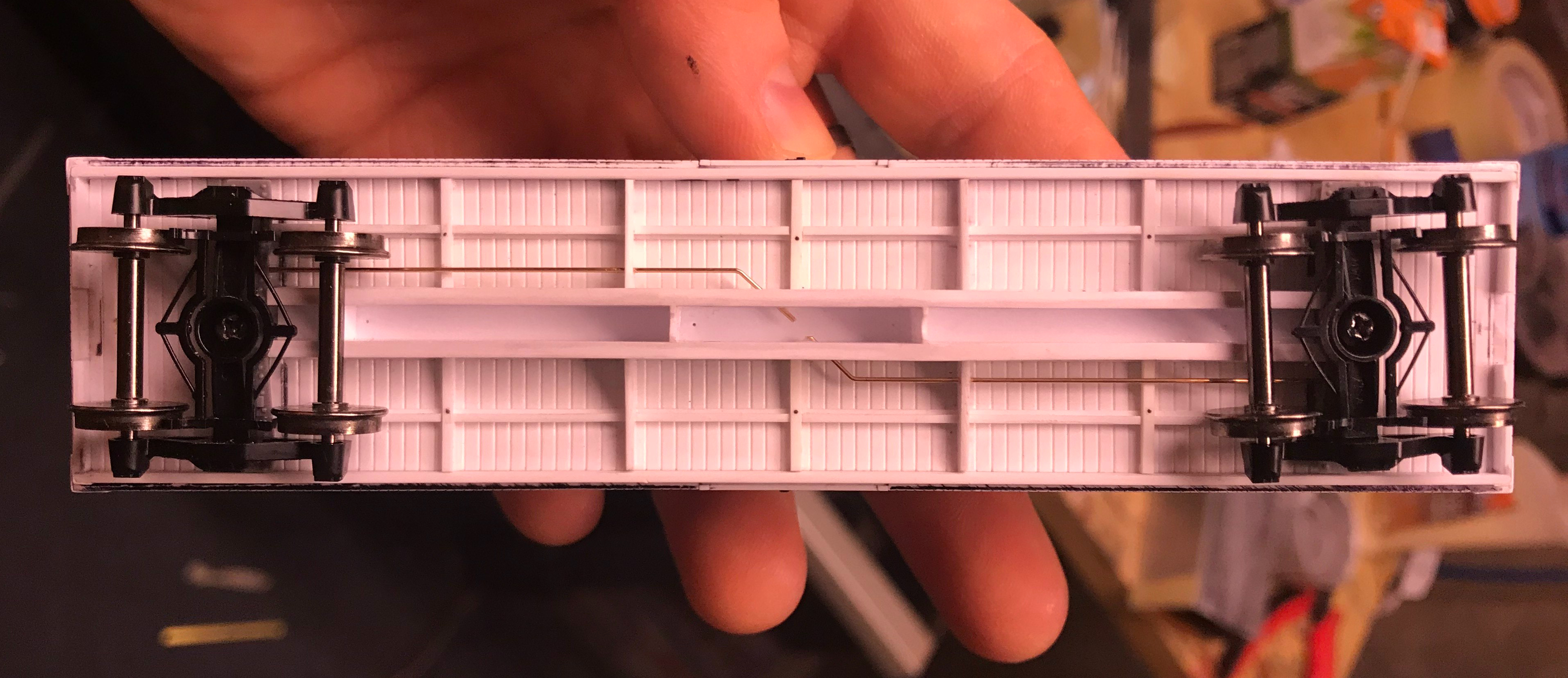
Once I was satisfied that I had removed all of the flash and mold release agents from the parts, I used 1-2-3 blocks, tape, patience and a minimum initial amount of CA to assemble the flat car sides, ends and roof into a 3D body shell. At this point, I turned my attention to the under-frame.

Completed under frame.

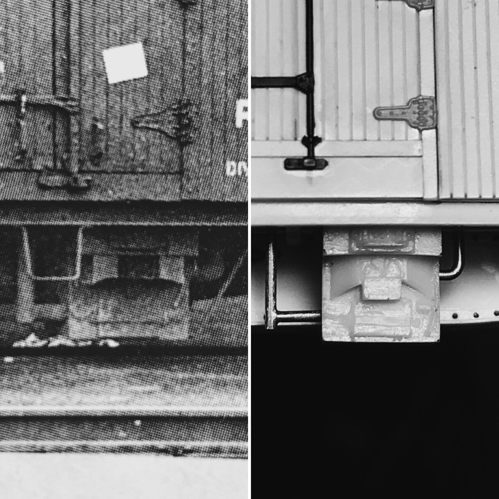
I used various sizes of Tichy phosphor bronze wire for the brake rigging. My standard approach for this is to use .015,” or .020″ wire for the train line (if I include it), .0125″ wire for the brake rods, .010″ wire for the air-lines and .008 wire for the retainer line and release rod, the latter which I usually wait and add after the model has been fully painted and the underframe has been glued in place. Tichy turnbuckles cut in half were used to simulate the Yarmouth Model Works brake levers’ clevis. The piping going to and from the underslung heater was added with piano wire. (In hindsight, you may have better luck with some Tichy .038″ PB wire as cutting piano wire this thick was NOT fun. I eventually had to use aviation snips.)

This photo shows how I used masking tape marked with lines to properly align the installation of the hatch rests.

Once I was happy with the underframe, I moved to the car body. As I mentioned above, I adhered mainly to the kit’s instructions, so I won’t bother getting too detailed. However, I will say out of all of the upgraded detail parts I used, I think the Des Plaines Hobbies Canadian Style 8 Rung Ladders and Yarmouth Model Works running boards made the most significant visual difference; I can’t recommend these parts enough for your next Canadian prototype build. 

The completed car, prior to painting.

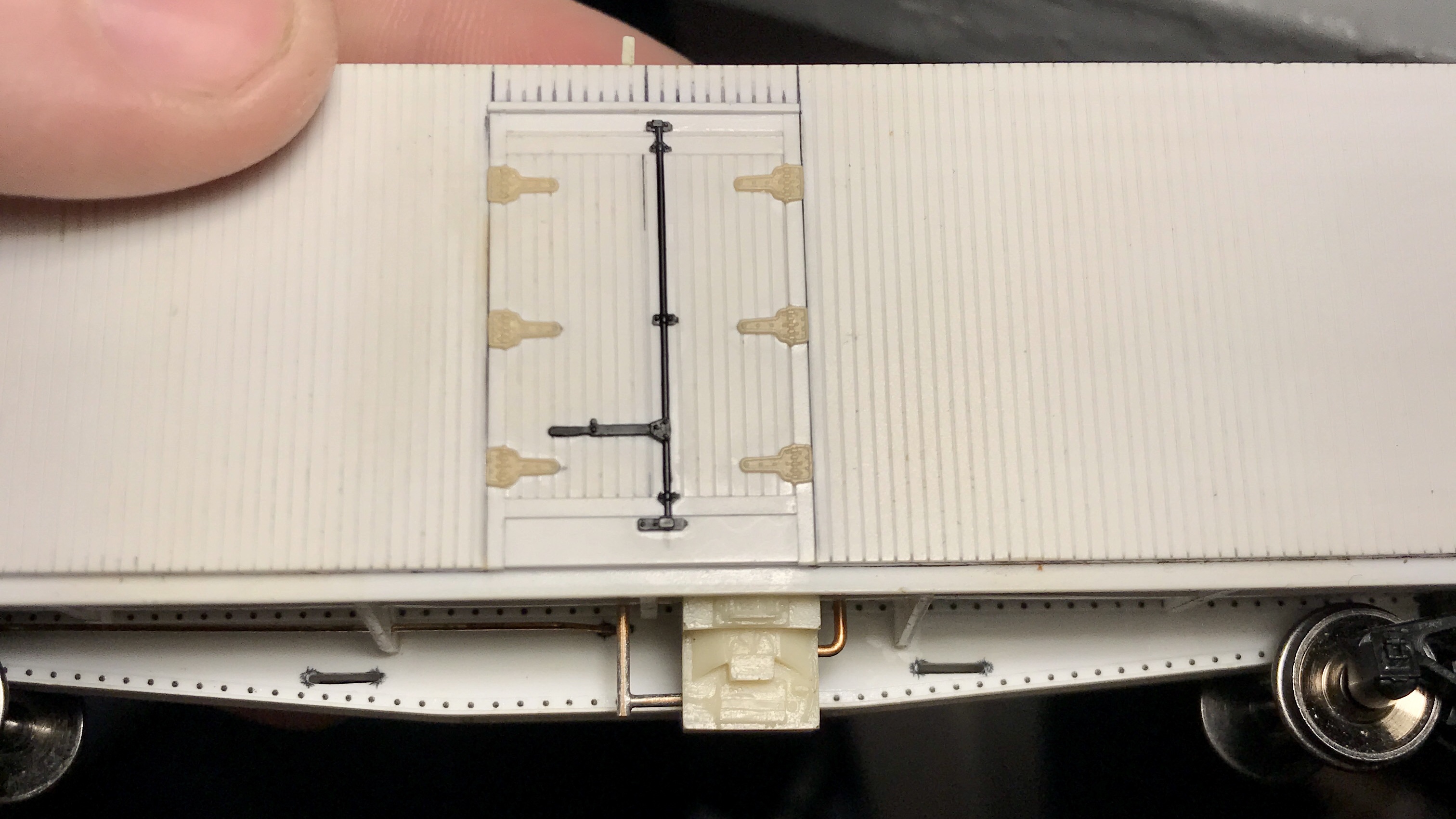
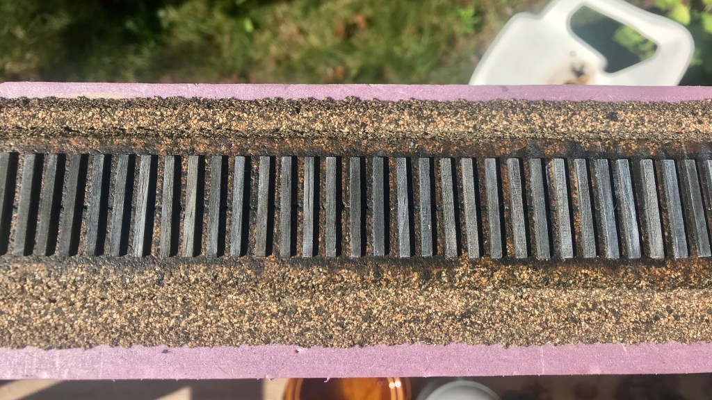
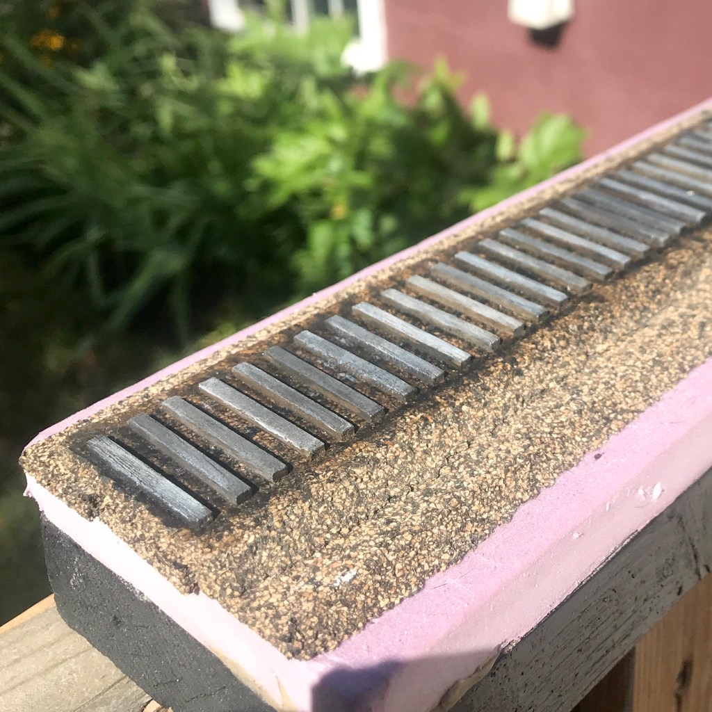
The hatch rests, tack + defect boards, brake wheel mount and jacking pads were built with Evergreen strip styrene. This was all pretty straight forward except for the hatch rests. The hatch rests included with the kit left a lot to be desired, so I used a tip I read on Pierre Oliver’s blog and made them out of strip styrene. A strip of 1×3″ and 1×6″ styrene was glued together in an “L” shape, which I then cut to equal sizes with my NWSL Chopper II. To have the hatch rests appropriately centred on the model’s roof, I laid out strips of masking tape on my workbench. I measured out the proper distances and drew lines on the tape to use as a guide, then taped the strips to the roof of the model and glued the hatch rests on with CA using the tape lines as a guide.

I primed the car with Tamiya Fine Surface primer- the bottom section of the car got primed with Oxide Red while the body got primed with Grey. I then loaded up my airbrush with black paint (VMA 71.057) and pre-shaded all of the panel lines, grab irons, brake rigging, running boards— virtually anything I wanted to stand out. I then painted the model, as usual, allowing the pre-shading to very lightly appear through the paint. The car’s bottom was painted #11 Red while the body was painted #11 Grey and all paints were Vallejo Model Air. To get #11 Red, I mixed 2pt VMA 71.105 to 1pt 71.038. For #11 Grey, I used straight VMA 71.045. After the model was painted, I used a #0 brush to paint anything attached to the body but falling under the sill (such as grab irons, stirrup steps etc.) #11 Red.

The lettering process.

Before lettering the car, I sprayed it with Testors Glosscoat and allowed it to cure for four days. The car was lettered with Black Cat Decals [CNR#209710-H] instead of the ones included. I also had some Speedwitch Media freight car chalk markings (highly recommended), which I later added. To get the particular car number and correct data information I wanted onto the model, I had to do some surgery on the decals. I wound up placing a lot of the numbers individually, which was time-consuming. After lettering was finished, the car was again sprayed with Glosscoat followed by Dull coat and allowed to cure.

Another angle of the completed car.
My completed kit (right) next to its True Line RTR counterpart.

All in all, I was very satisfied with how this model turned out. I gained a lot of experience and tried many new-to-me techniques.

Next time I’ll be giving a rundown on a Yarmouth Model Works 40ft CNR boxcar I completed a year ago.

Thanks for reading!

CM


COMMERCIAL DETAIL PARTS USED:

  • “HO Canadian 8 Rung Ladders” / Des Plaines Hobbies [DPH-2003] x1 Package
  • Laser Cut 40′ Wood Running Board w/ Laterals & Etched Brackets / Yarmouth Model Works [YMW-255] x1 Package
  • “Eyebolt No Collar” / Yarmouth Model Works [YMW-500] x1
  • “Eyebolt w/ Collar” / Yarmouth Model Works [YMW-501] x1
  • “Bracket Grab Drilling Template” / Yarmouth Model Works [YMW-502] x1
  • “Brake Levers, Set of 10” / Yarmouth Model Works [YMW-503] x1
  • “AB Brake Set” / Tichy Train Group [#3013] (included w/ kit) x1
  • “Turnbuckles” / Tichy Train Group [#8021] x1 Package
  • “Straight Side Mount (Stirrup)” / Tichy Train Group [#3038] (included w/ kit) x1 Package (Tip: After all of my upgrades, I do find these are left looking a little out of scale. Perhaps an A-Line product would have been better suited.)
  • “HO 22” A.A.R. Air Hoses w/Brass Brackets” / Hi-Tech Details [HTD-6040] x1 Package
  • “HO Blackened Brass Chain / 45 Links Per Inch” – Crescent Locomotive Works (eBay seller)
  • “Barber S-2 50-Ton Trucks” / Tahoe Model Works [TMW-213] x1 Pair
  • “Semi-Scale .88 Wheels” / Intermountain Railway Company (came w/ trucks) x4
  • “Scale Whisker Metal Couplers Med Centerset Shank” / Kadee Quality Products Co [#178] x2
  • “Side Grab Irons – Red Oxide” / Kadee Quality Products Co [#2250]
  • “Scale Snap-Together Gearboxes and lids” / Kadee Quality Products Co [#178] x2
  • “Westinghouse Single Pressure Retainer Valves” / Precision Scale Co [#3263] x1
  • DECALS:
  • “CNR 8 hatch reefer leaf scheme 1953-1961” / Black Cat Decals [CNR#209710-H]
  • “Freight Car Chalk Markings” / Speedwitch Media [D135]

SCRATCH-BUILT PARTS USED:

  • Hatch Rests x16 – Scale strip styrene cut with a chopper tool and glued together in “L” shape
  • Defect Boards x2 – Scale strip styrene cut and assembled
  • Tack Boards x4 – Scale strip styrene cut and assembled
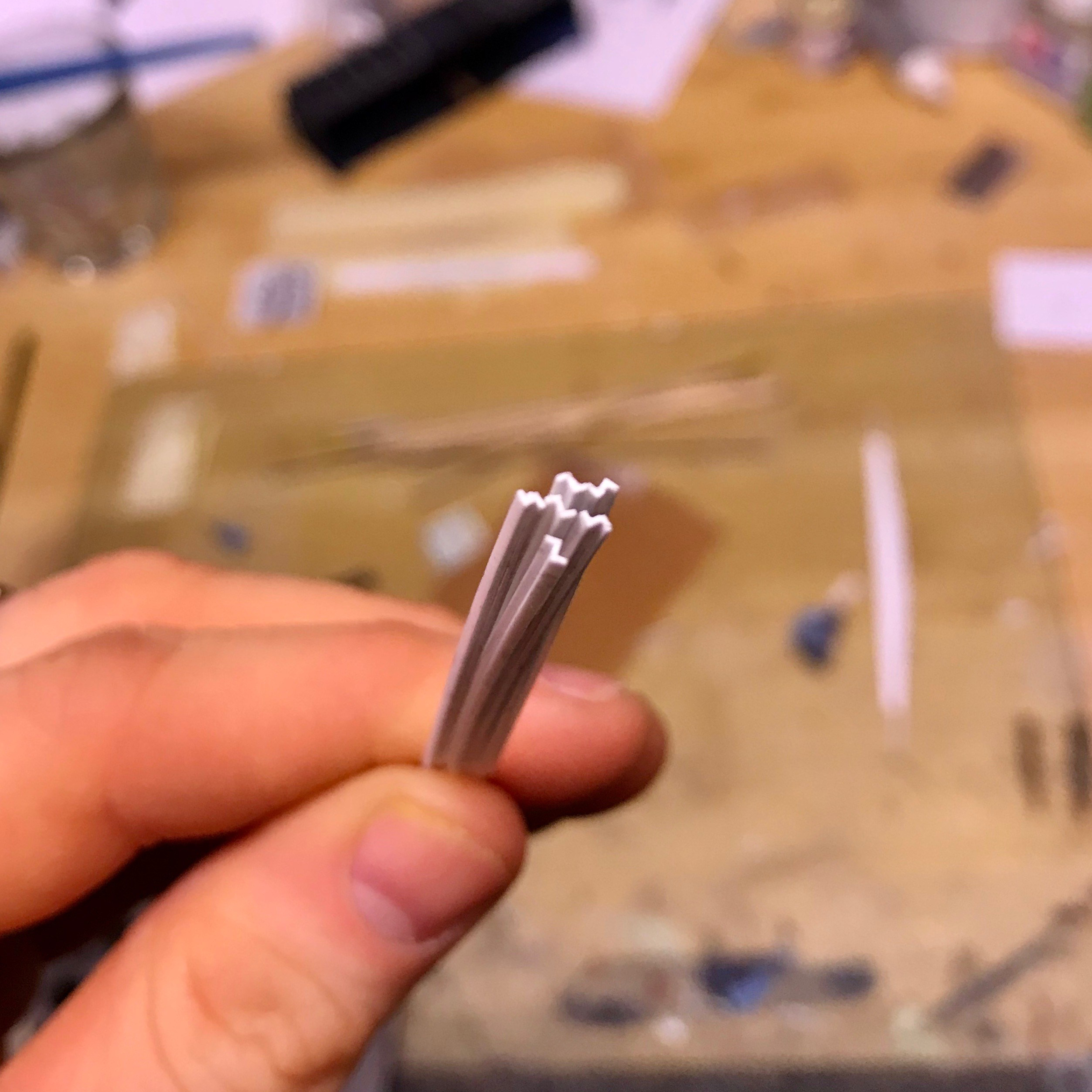
  • Drain Spouts x4 – Tichy PB wire inserted into holes drilled into car bottom and glued from the inside. Square styrene strip cored out with a pin vice and then slid over the PB wire, dab of CA secures the styrene to the bottom of the car and wire.
  • Brake Lines – .010 Tichy PB wire measured, cut to size, bent with pliers, inserted and glued into brake components.
  • Brake Rods – .0125 Tichy PB wire cut to size and inserted into Tichy turnbuckles which were cut in half and thinned down to simulate the clevis.
  • Coupler Cut Levers x2 – .008 Tichy PB wire cut and bent to shape. Inserted through bracket on car end and through YMW “Eyebolt No Collar” above coupler.
  • Release Rod x1 – .008 Tichy PB wire cut and bent to shape. Inserted through hole drilled into sill and through YMW “Eyebolt No Collar”, drilled and inserted into triple valve.
  • Stand-offs for DPH 8 Rung Ladders x8 – Strip styrene cut and glued to ladders, then ladder glued to car.
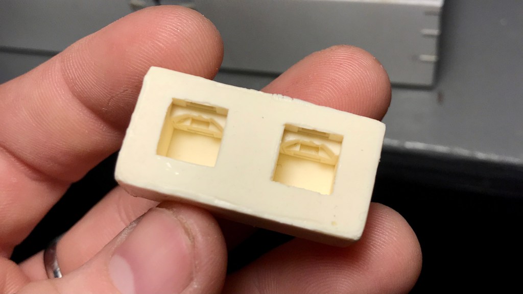
  • Underslung Heater Piping x2 – Music wire cut, bent and inserted through holes drilled into the sides of the underslung heater casting and through holes drilled into the car floor. Glued from the inside of the car with JB Weld 2-Part Epoxy (the 15-Minute stuff)

Scratch-building CN’s 40′ Wood End Bunker Reefers PT:5 [Underslung Charcoal Heaters & their Piping]

Small update coming at y’all- and while it’s small, the process behind this was large.

Last night, in the final hours of my 20s, I installed the underslung charcoal heaters and their piping onto Reefer cars’ underframe.

The heaters were resin copies I cast of a certain manufactures underslung charcoal heaters that I could not purchase individually from a kit. I cut a notch out of the previously installed Z-bracing and then affixed the heater right to the car floor with CA.

The piping was .032” Tichy PB Wire threaded through the car floor into small holes drilled into the heaters. I made the “T” joint by first filing the ends of the cut wire totally flat, then used masking tape to hold the wires together in the desired formation on top of some scrap wood. Flux was applied, and solder was liberally applied to the joint. I cleaned it up with 400 grit sandpaper, rubbing alcohol and a wire brush.

The bracing/strapping that holds the heaters to the car floor on the prototype will be installed after the final under-frame installation is made


One of the first things I had to consider before taking on this project (almost a year ago !!!) was the availability of certain parts that would be rather difficult to scratch build- the big concerns being the roof hatches and the underslung heaters.

Well, I was able to find suitable hatches to use (Details West RH-1003). Still, underslung heaters were going to be a different story.

I tried emailing a certain resin kit manufacture multiple times to see if I could purchase some of their cast underslung heaters that they include in their Reefer kits but received no response.

Second, I took to Shapeways to see what I could find. I placed an order with a certain shop for some heaters that looked promising, but when I received them- though they were nice, they just didn’t look as nice as the other manufacturer’s part. And that just couldn’t do.

So, as a last resort, I raided a couple of unbuilt 8 Hatch Reefer kits I have in the closet, got a casting kit at Great Hobbies and cast my own resin copies of the underslung heaters; something I’d never done before.

I’ll spare the casting process, but I’m happy with how they turned out. And while it was a minor headache to not just buy the parts I wanted, this turned out to be a great learning experience, and I’ve learned a new skill.

[A note on ethics: I wouldn’t condone doing something like this (even for personal use only) if the parts in question were still in print and/or readily available. You should always support hobby shops and manufacturers whenever possible. Don’t be a dink.]

The ties that bind…

Ok. So, before the world exploded my focus in Vernon River land was more or less on preparing for the laying of ties, ballast and track.

For a man who hasn’t even laid flex track before, you could imagine how deep of a daunting rabbit hole this could be.

It has been my full intent since Day 1 with not only this project it’s-self, but my modelling as a whole to hand lay my track. It just seems like the right thing to do and nothing looks exactly like wood, but actual wood.

Instead of just going in blind and starting to lay track on my actual bench work I figured it might be fun / a good idea to teach myself this group of skills by building a display / test track.

So that’s what I did.

I ordered a “Ultimate Track Sample Starter Pack” with Code 55 rail and 8ft ties from Proto87, snagged a 1×3 that a buddy of mine had from his old deck, got some 1/2in extruded foam left over from a different buddy’s garage build and got to work.

I’ll go over the actual test track it’s self another time. What I want to show off here are my ties.

Hunter Hughson has a great post on Weathering Ties with Acrylic paints over at his blog that I more or less followed to a tee, and man am I ever happy with how they turned out. The only thing I changed from his process was how I went about beating up the ties. Instead of a dental pick, chisel tip and #7 Exacto blades I used a dental pick and wire brush at the suggestion of Chris Mears.

I had the idea to perhaps switch it up and represent a later era with my test track; say the late 70s or early 80s, where tie plates would be more prevalent on the prototype [AKA a excuse to use more of the beautiful Proto87 tie plates that came with the sample pack]. However, I’m leaning back to sticking with the late 50s. I’d still perhaps throw a couple tie-plates down here and there on newer looking ties.

Next up will be ballasting. If I stay with the late 50s it’ll be cinders, if I go with the late 70s / early 80s it’ll be a mix of crushed rock.

C.M.

Scratch-building CN’s 40′ Wood End Bunker Reefers PT:4 [Rivets & installation of the centre sills, z-bracing and crossmembers]

Well, it’s been longer than I would have liked between updates.

This whole COVID-19 mess has certainly affected every one of us, and us in the aviation industry, especially in terms of employment. My employer has placed myself and roughly 15,000 other of my union brothers and sisters on off duty status, which has admittedly been hard to comprehend given how quickly all of this has erupted.

Without getting too personal, I’ll just say this whole mess really hasn’t left me with much motivation to write. However, as the dust of our new reality begins to settle, I’m starting to feel a little better. That said, this post isn’t nearly as beefy as I’d like it to be, and I must apologize.


Progress has continued on the reefers, and I’m really starting to get excited about where this project is headed. The fishbelly sills have been riveted with MicroMark surface decals and installed along with the z-bracing, cross-bearers, cross-members and train line.

IMG_1447.jpeg

After installing the z-bracing (which I put on the wrong way somehow! whoops!), I used my UMM saw to cut through the bracing and installed the cross braces and cross members. I went with 4×4″ Evergreen for the cross members and used my Cricut Maker to cut the cross bearers from .030″ Evergreen sheet. The cross bearers will receive a 1×6″ cap over them after the floor is glued into the cars.

60753719966__51C9BE7E-28A4-4EF0-A7AB-C59859C6DA26

With the sill, z-bracing and supports installed I figured now would probably be a good time to install the tramline as it needs to be threaded through the cross-bearers. I bent .020″ Tichy PB wire directly over top of the scaled down general arrangement drawings, cut it into two pieces and installed it into the car with CA. This was repeated for both cars.

IMG_1448

Another view of the under frame.

Next time, I intend to make a drill jig for the side and end grab irons using the engraving tip on my Cricut Maker. I plan to design the jig in 2D with CAD, engrave it onto a .010″ brass sheet (or a soda can), cut it out, fold it against a vice and then use my pin vice to punch the holes before using it to drill out for the grabs.

We’re all facing a lot of stress right now… I encourage you to take some time and work on or run your models. We all need to get our minds off of things. Please wash your hands and stay home.

CM

Scratch-building CN’s 40′ Wood End Bunker Reefers PT:3 [Fabricating Fishbelly Centre Sills and Z-Bracing]

After a brief break from the CNR Wood Reefer project, this weekend seemed like a good opportunity to get back to it; with the recommended social distancing and all. Might as well use a not-so-good situation to have some fun at least, right?

The next thing I needed before proceeding with the underframe of the car was Z-Bracing. The general arrangement drawings show two lengths of Z-bracing running end to end of the car. The problem I faced here was that Evergreen does not make Z-angle small enough, but I didn’t want to mail it in and use just a plain old strip in place of the Z-angle.

Luckily, while cruising around the internet looking for pictures of scratch-built fishbelly centre sills I happened across Chris van der Heide’s blog. Lone behold Chris had run into the same problem as me at one point and took the time to detail how he fabricated and used a jig to create his own Z-Angle stock in this post. I decided that this is how I would proceed.

The jig was not at all hard to make and the process of feeding the three strips of styrene (HO scale 1×3″ on the top and bottom and 1×2″ as the web) through the jig was made easier by brushing a little bit of powdered graphite into the hole as a lubricant.

IMG_1332

The final product.

As you can see the finished product is just as good as anything you could buy on the market. Thanks for your help Chris even though you may not know you helped! LOL. Make sure you check out his blog post for a better explanation of how this was done.

With the Z-Bracing out of the way the other major component needed for the underframe was the fish belly centre sill.

First, I used the scaled-down general arrangement plans as a guide to drawing the general shape of the sill plates in TinkerCad. Then, I used my Cricut Maker to cut the fish belly sill plates out of .030″ sheet styrene. The great advantage to using the Cricut for this purpose is that all of the sill plates will be accurate and of the identical measurement. One disadvantage is the cutter does create a bit of a burr around the cut but it is easily cleaned up by carefully using a single edge razor blade to slice it off. The Cricut Maker is an amazing machine and deserves a post of its own. I see a lot of potential for this machine in the hobby of model railroading…

After the sill plates were cut and cleaned up I added 1×6″ Strip to the bottom of the plates by pushing the strip and plate against 1-2-3 blocks and gluing them together. Then, I added 1×4″ strip to the top of the plate as well as 1×3″ along the bottom of the plate where it meets with the 1×6″ strip.

After all of the sill plates were built, I glued the tops of them to a piece of 2×12″ strip to create two full fish belly sill assemblies- one for each car. When the glue dried, I wedged strips of 2×12″ styrene vertically between the plates to prevent them from warping inwards. I trued the edges up with my NWSL true sander.IMG_1327.jpeg

One of two completed fishbelly centre sill assemblies.

IMG_1331.jpeg

While the fishbelly isn’t glued to the car floor in this photo, this shows how it will look attached to the car.

I’m very pleased with how the fish bellies turned out. Once they are glued to the model a strip of 1×3″ strip will be glued against the car floor and the side of the sill plates to create an “L” channel with the 1×4″ plate on the sill.

I will use MicroMark surface decals for the rivets and I’ll likely apply them to the sill before gluing it to the cars (with the exception of along the previously mentioned 1×4″ strip.)

Next time I will glue the centre sills onto the car floor, install the z bracing and fabricate and install the cross ties/cross-bearers. After that, it will be time to install the underslung heaters and install the brake rigging (my favourite!).

[Worth noting: the underslung heater may become a project in its self, 3D printed part which may end up being molded and cast as a precaution- I don’t entirely trust the chemical stability behind Shapeways’ Fine Detail Plastic. We’ll see.]

Thanks for reading,

CM

Special delivery… (70 Tonner decals)

Just wanted to poke my head in and give a little mail-day update..

Backstory: Last fall I designed and 3D printed a accurate footboard assembly for my long-stalled Kaslo 70 Tonner project. This was a detail that had been bothering me for some time and I just couldn’t seem to get it right by scratch-building with styrene. This 3D printed part gets me over that hump, but in order to finish the project I still needed decals…

Receiving the test parts from Shapeways was the inspiration I needed to finally get off my behind and get decals made so I could finish the project.

STR21235a.001.aa.cs

CNR #38 at the Moncton, NB diesel shops. CSTM Collection.

Shortly before Christmas I began talks with Bill Brillinger from PDC.ca to make a custom set of decals for the ‘simplified’ second iteration of the green and gold livery the CNR 70 Tonners wore. I mailed him some reference material and to work he went.

After a few weeks of back and forth, I was very excited to see the PDC.ca envelope full of 70 Tonner decals arrive in my mailbox today.

IMG_1274.jpeg

As you can see, the decals turned out beautifully. Bill is an absolute joy to work with and he nailed what I was looking for. The decal set will do three locomotives with the ability to label any unit on the roster, although not all of them got this paint job.

While my super-detailed 44 Tonner will see lots of action on the layout, 70 Tonners were just as common and I’m excited to finish this project so I can run 70T #38 in mixed train service.

CM

Finding inspiration from a later era

IMG_1253.JPG

Loading potatoes at St. Peters Bay, PE – Late 60s 1970s? Jim MacKinnon collection.

While looking for photos of tractors on The Prince Edward Island Railway Facebook page, I came across this photo of a reefer being loaded with potatoes at St. Peters Bay.

The author of the post incorrectly labelled it as the 1950s, but as we know by the noodles on the boxcars, this is post-1961. Further, the American reefer car’s presence makes me believe it might even be the late 60s or 1970s.

While this photo isn’t within my era, it really strikes some inspiration. The railway on PEI had many public sidings or team tracks- but not many of them had permanent loading ramps. The public siding at Vernon River did not have a loading ramp.

This scene might as well be Vernon River. It would be a very similar scene. The farmer or merchant backs truck or trailer right up to the car, plywood ramp bridges the gap, potatoes are transferred across- probably a lot of the time “hand-bombed

.”

I am very grateful to find this picture. It will be used as a direct reference to develop the scene and the public siding.

As mentioned at the beginning of this post, I’ve in passing begun to research era-appropriate vehicles for the layout. My first purchase was an Alloy Forms 1947 Clark Forklift, which will live at the Co-Op Warehouse… I just need to figure out the proper colour to paint it.

I’ve mentioned this before to friends, and you may disagree, which is fine. Still, I really find that too many vehicles are the easiest way to break a layout’s realism. Luckily for my era, Route #3 wouldn’t have been nearly as busy as it is today, hell it probably hadn’t even been paved to long before- there won’t be any vehicles on it, and that won’t look out of place. I’m thinking a car or two parked at the station, a truck parked at the warehouse, a tractor and potato trailer along the siding and maybe an abandoned truck in the corner of a farmer’s field will be sufficient.

CM

Vernon River Co-Op Warehouse: a study on shared building plans.

IMG_1210

The former Vernon River Co-Op Warehouse built in 1947. July 2013. Chris Mears photo, used with permission.

Since the very conception of this layout, a mystery has been at the back of my mind. That is the mystery of the Vernon River Co-Op Warehouse.

Perhaps not as much of a mystery as a minor annoyance. You see, the photos I have are only but a tease only providing partial views of how this building looked while it was still rail-served.

There is one fact working for me: the building still stands today- rails to trails use it as a workshop. Having an accurately sized model will not be a problem; however, its freight doors and roof vents have been removed, and the roof and siding have been replaced.

I’ve reached out to local area Facebook groups to find a better photo of the building with its freight doors still intact, to no avail. I’ve reached out to the archivist at St. F.X. University, which does have a giant photo collection of Co-Op buildings, PEI included- to no avail. (One avenue I have not yet explored is to contact rails to trails and see if I could be allowed inside to see if the door framing is still visible.)

This information gap has mostly left me to fill in the blanks myself.

However, just this morning, I had a bit of an “ah-ha” moment.

I don’t know why this didn’t hit me before now, but I had already been aware of direct evidence that the co-operatives routinely shared building plans, being co-operatives and all. One such example is the Co-Op Potato Warehouses at Morell, Tignish and Souris being nearly identical.

Could the Vernon River Co-Op warehouse be a shortened version of these other warehouses?

IMG_1199

Morell’s Co-Op Warehouse. Year and photographer are unknown. St. F.X. University Archives.

20935076_1902309463423996_4088096629602011681_o.jpg

Souris Co-op Warehouse. Steve Hunter photo, year unknown.

IMG_1209 copy

Tignish’s Co-Op Warehouse. Year and photographer are unknown. Note that the building is nearly identical to Morell’s warehouse, a county away.

What caught my attention is how similar the front of the Morell warehouse looks to the front of the Vernon River warehouse. The large double door and loft door are of identical construction. The chimneys are similar. While in different locations, the man-door and window are of very similar structure. What we can see of the first freight door shows us that these doors are also very similar, if not identical, to the Morell warehouse.

To corroborate my theory, I took to Google Earth and went back in time to 2015, when the Morell warehouse still stood. Now, the two warehouses’ lengths obviously differ- we don’t need Google to tell us that, but I was most interested in finding out if the buildings were the same width.

I’ll be the first to tell you that Google Earth’s measurements aren’t always so accurate (they even admit this themselves). Still, I figured that if I measured the buildings from a satellite image taken on the same day, I’d be able to figure out if they were the same size.

What I came out with was this:
Morell warehouse= 43.24′ x 122.82′
Vernon River warehouse = 44.91′ x 82′

Given Google’s inaccuracies and satellite imaging variables, the widths are very close indeed. I’ll take that as a win.

So now we know that the Vernon River and Morell warehouses were, in all likelihood, the same width. The similar width dimension, look, owner, and use of the building make me feel comfortable using the Morell and Souris photos as a reference for the Vernon River build. The Morell and Souris photos, along with a scale drawing of the Morell warehouse Steve Hunter gave to me, will most certainly get me most of the way there.

Without a photo showing the Vernon River warehouse’s entire side, we don’t know how far apart the two freight doors were.

I can figure this out in two ways:
– Obtain permission to enter the warehouse as it stands today and see if the door framing is still visible from the inside.
– Measure the outside of the warehouse and use the 1958 air photo to scale out the door centres.
These methods will have to wait until the snow melts, but I’m happy having figured out the process I’ll have to follow.

One final question I may never have a firm answer on involves the relationship between the truck door and the foundation.

In the Souris, Tignish and Morell photos, the land is built up to the top of the foundation to meet the truck door- meaning the truck door doesn’t go through the foundation. However, in the Vernon River photos, it appears as if the foundation has been cut to allow for a taller truck door. The man door placement above the foundation caught my suspicion and made me believe that the ground was initially built-up like the other warehouses. For some reason, the door’s height needed to be increased, so the foundation was cut to allow for this.

As you can see in the 1981 Vernon River photo, it looks as if a whole new door frame has recently been installed and the earth around the foundation excavated. The man door remains above the foundation. Perhaps this is all the evidence I need.

After studying the images, I have concluded that it’s very likely that at some point, the foundation was cut to accommodate a taller truck door- most likely in the early 80s. Wouldn’t the man door be cut into the foundation if the building was initially built like this? I feel confident I can model the door as shown in the Morell photo, with it being accurate.

Unfortunately, I’ll have to wait until the spring to further this research as it requires a field visit. Still, I feel confident that I have most of the information I’ll need to scratch-build this building.

If you’ve stuck with me this long, thanks for reading.

CM

A sunny winter’s day prototype visit.

After Wednesday’s hangout with Taylor, Chris and David I was feeling pretty pumped about the direction of things.

That feeling was only amplified after a Saturday afternoon spent in New Brunswick operating on Doug Devine’s Island Central Railway and Steve McMullin’s Carelton railway.

Even though we we’re very much in the dead of winter here on Prince Edward Island, spring was definitely in the air this Sunday afternoon. I couldn’t resist making the first of what is likely to be many visits to the prototype location.

I can look at photos all day but to catch onto the feeling of the layout I really needed to get out to Vernon River its self and get an idea of how the land lays in 1:1.

Instead of photos, I thought it would be easier to just make a short video which you can find right here:


I will return when the snow melts and again in the summer. I plan to take many photos of the right of way,  trees, buildings, farmers fields and farm roads in the area to get a good idea of how I’ll model them.

C.M.

Testing the track plan.

A little update…

Taylor, David, Chris and myself got together in Taylor’s shop on a Wednesday evening and laid the paper plan out on the modules. It was nice to have some knowledgable friends on hand to help me properly orient the plan and decide where the staging cassettes would go.

Of course, with a huge plan on the table we just had to put some cars and switches on it to give it a bit of a “look” test.

Seeing this plan come to life is so exciting. I was really excited to see the track plan on the modules, but I got even more excited after I saw the track plan with the cars on top of it.

A lot of work lies ahead but I feel really great about how it’s all coming together. This layout really is going to be more than a nice thought, this is really happening.

I will have the paper plan reprinted to include the high-res 1958 air photo I purchased from Natural Resources Canada, after that it will be time to finalize the orientation of the staging cassettes..which means road bed isn’t far off.

Hopefully next weekend Taylor and I will be able to finish off the benchwork.

CM