In the early 1920s, during the founding years of the Canadian National Railway, a wide array of freight and passenger equipment was inherited from its predecessors. Amongst these inherited cars was a venerable fleet of flat cars of steel construction, initially built for Canadian Northern Railway (CNor), Canadian Government Railways (CGR) and Grand Trunk (GT).
These steel cars were the subject of a duo of Stafford Swain articles entitled “CNR Pre-War Steel Flat Cars – Part I” [CN Lines Vol 5, N3 – focuses mainly on prototype information] and “CNR Pre-War Steel Flat Cars – Part 2” [CN Lines Vol 5, N4 – focuses primarily on building the cars in HO scale, includes scale drawings].
As I’ve mentioned before, you can buy a thumb drive that contains every single back issue of CN Lines, and these two articles were worth the price alone.
The articles cover the A-1, A-2, A-3, A-4, B-1, B-2, C-1 and D-1 series cars- all of which can be built with relative ease from Tichy #4021, Athearn donor cars, or just straight up scratch-built.
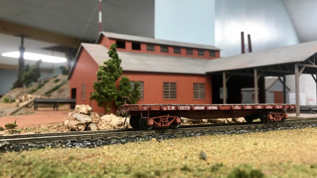
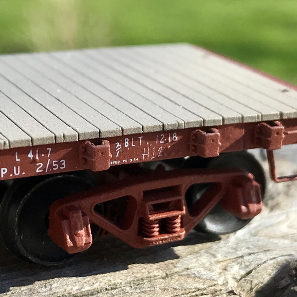
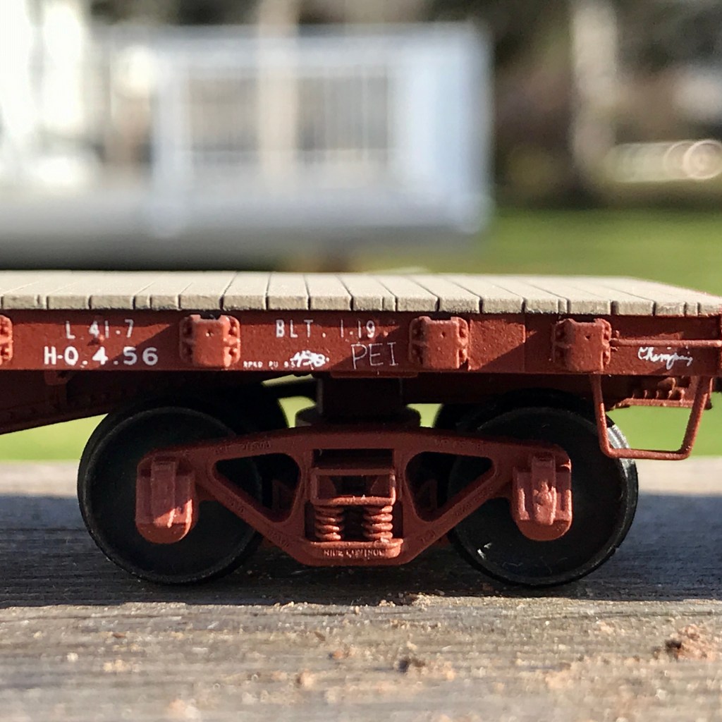
I decided to build two “A-3” cars: #651731 from the CNor order and #652125 from the CGR order, using Tichy #4021 as a starting point. Both orders were handled by the Eastern Car Company of Trenton, NS, just 66 kilometres as the crow flies from Vernon River, PE, in the winter of 1918 / 1919.
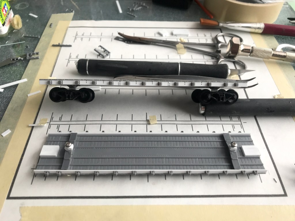
I began by first installing 2×8″ styrene strip substrates in substitution for the kits supplied side sills. Next, I raised the height of the car by 6″ by first installing the kits provided truck bolsters and then a 6″ styrene block at the pivot point of the bolster. I also added a 6″ styrene block where the coupler pockets would later be installed.
At this point, I used a CAD program to create and print a template to aid in the positioning of the stake pockets on the scratch-built side 1×10″ sills. The spacing measurements for the stake pockets are provided in Stafford’s article.
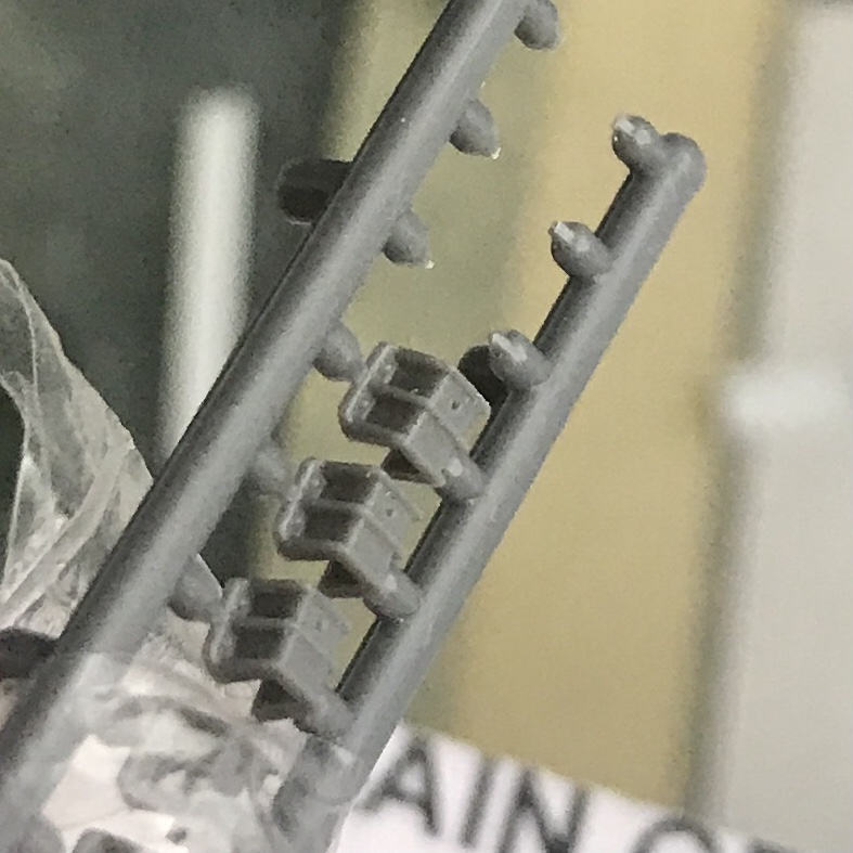
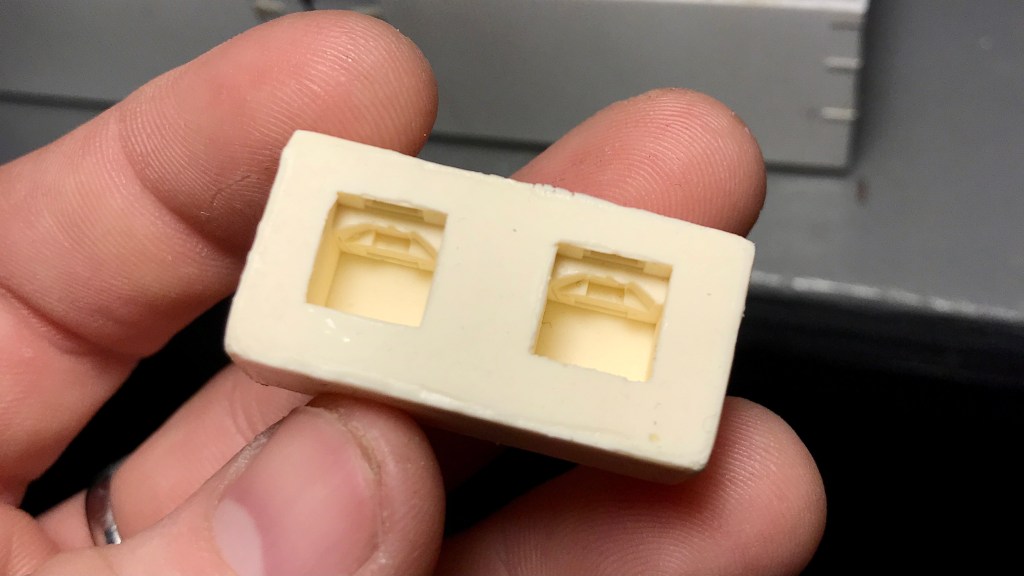
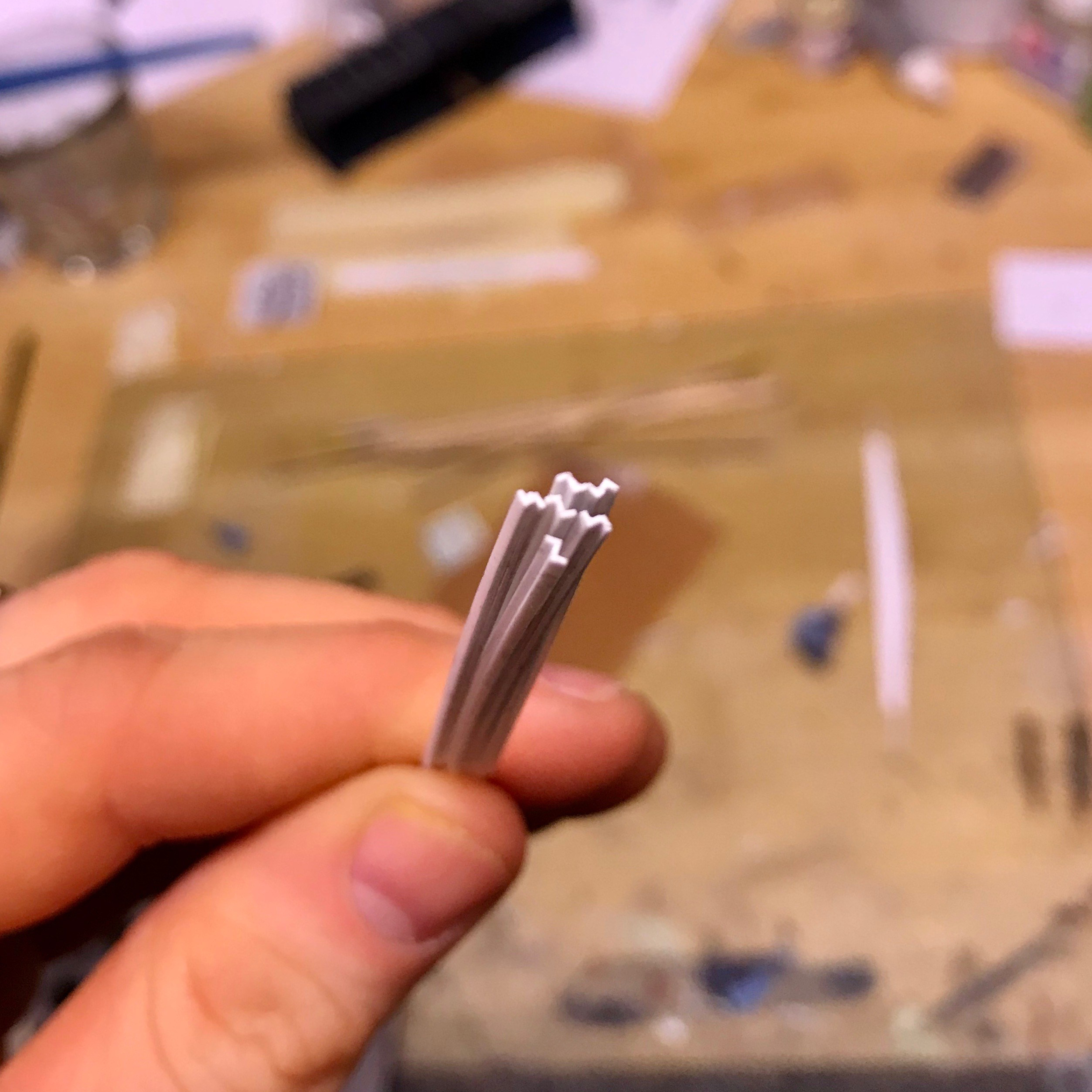
The stake pockets as supplied. 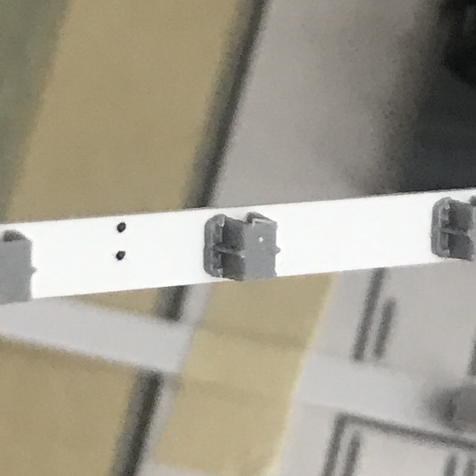
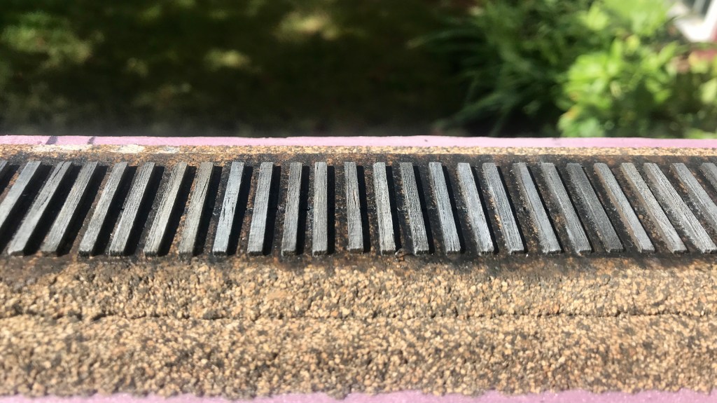
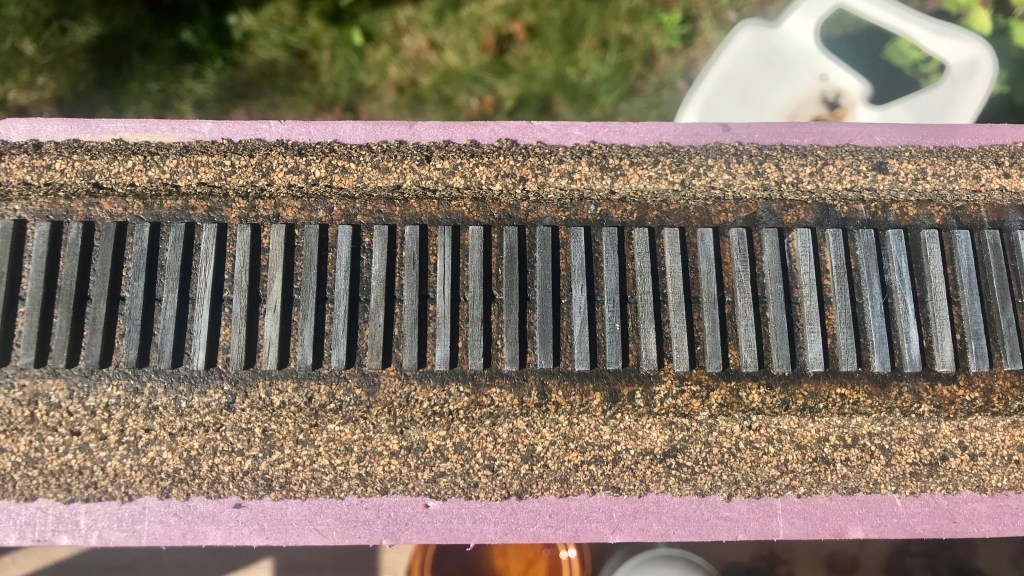
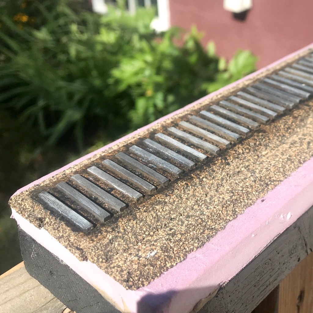
The stake pockets after modification.
The kits provided stake pockets are inaccurate for the CN prototype as supplied. This was remedied by filing off the details on the front of the pockets while still attached to the sprue. After this was done, I used the previously mentioned template taped to a sheet of glass to aid the placement and installation of 13 stake pockets per sill.
Once I had 4 side sills created, and I was sure the glue was dry, I went back with a #17 chisel blade and removed the remaining “u-bolt” details from the top and bottom sides of each stake pocket. With all of these details removed and a coat of Tamiya Extra Thin styrene cement quickly applied over the entire pocket to dissolve any leftover detail fragments and “melt” everything together, the stake pockets now more closely resembled the cast metal pockets of the CN prototype.
With the significant structural work of the side sills complete, I glued them to the car and then drilled out the holes for the grab irons. At this time I also drilled out end pockets in the cars decking. To clarify: the reason I used a 2×8″ strip for the substrate and then 1×10″ for the actual sill was to create the illusion of a more “thin” side sill if the car is viewed from track level while still maintaining the overall thickness of the kits supplied sills.
Next, I began work on modifying the supplied centre sill.
I began by filling in the notches in the kits sill sides that normally accept the kits’ super deep cross-bearers. After these “notches” were filled in with styrene and filed level, I installed the centre sill.
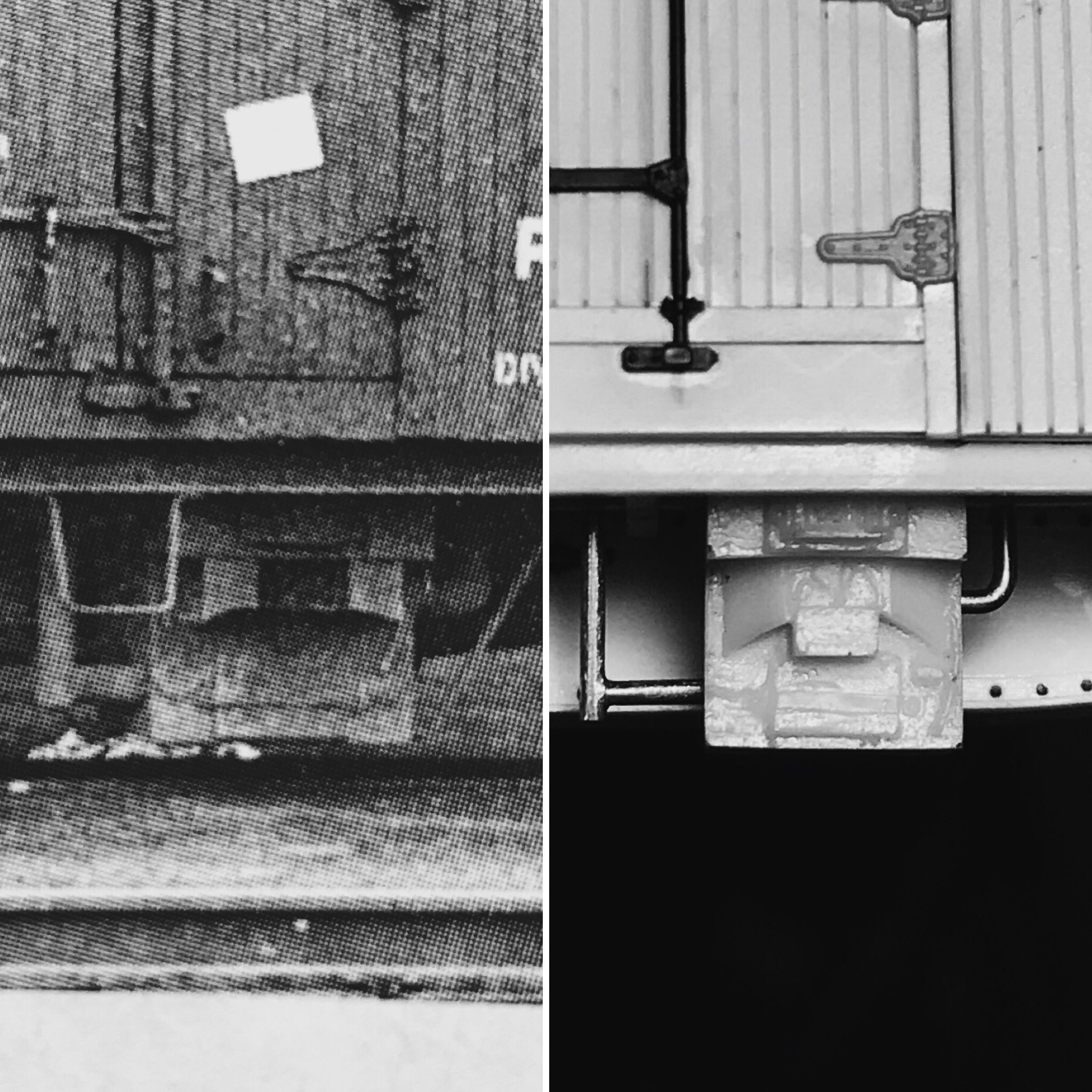
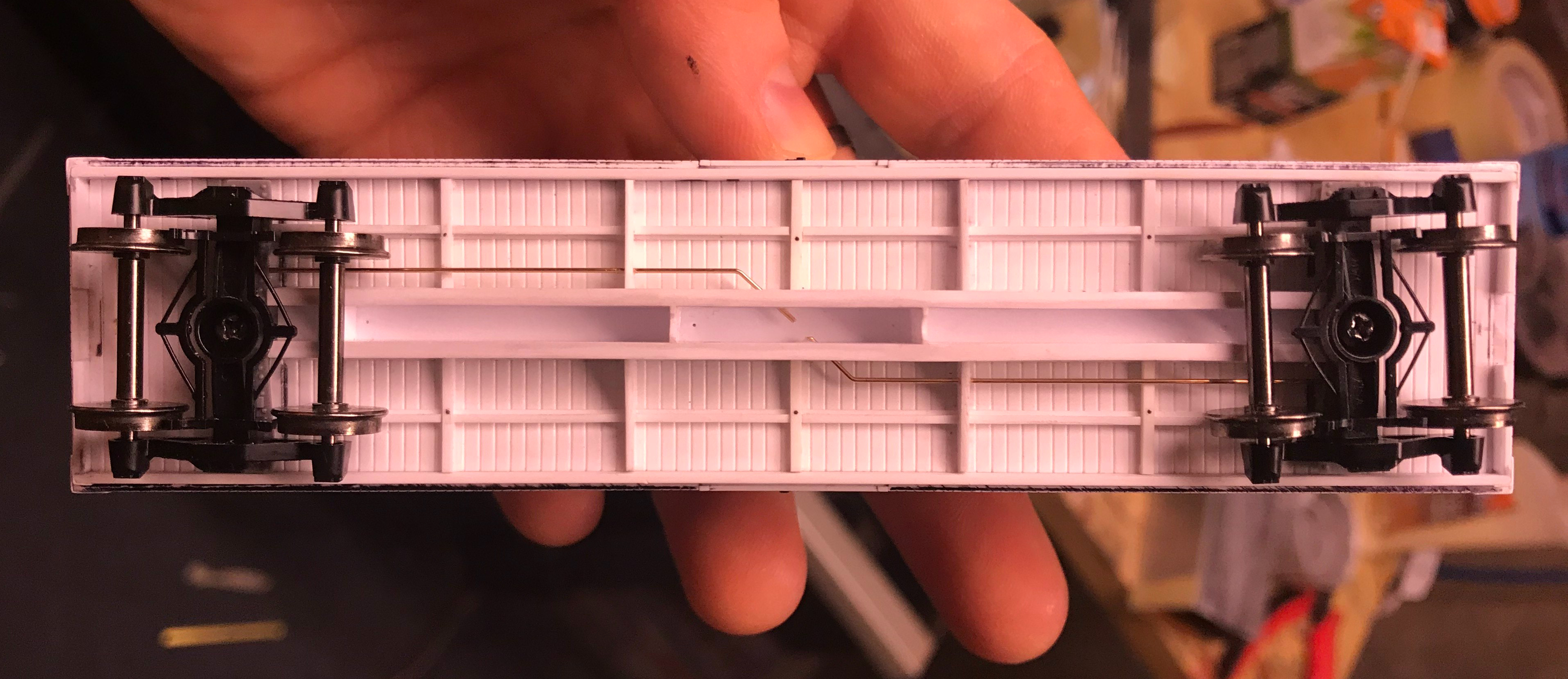
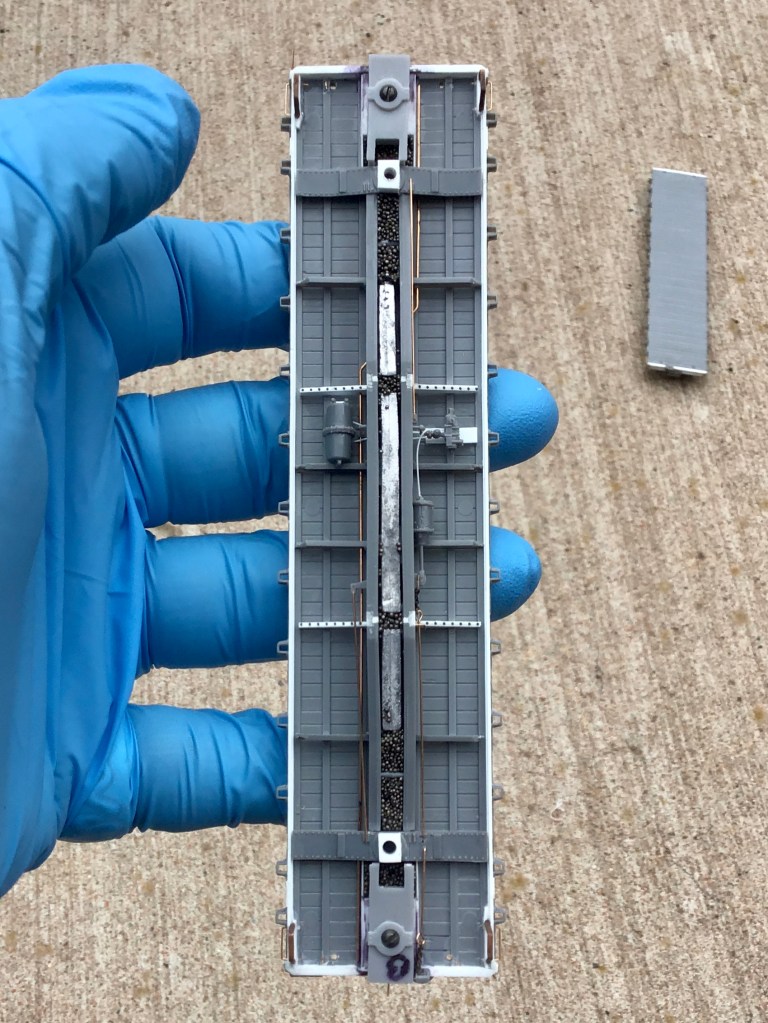
After the centre sill was installed, the next task was to establish an AB brake system and its piping in place of the kits provided K system. Because all of the drawings in the article have the K system, I had to turn to prototype photos to figure out where everything went. I mounted the brake cylinder to the mounting bracket for the K system, and then with a prototype photo, figured out the location of the air tanks. With these two locations known, it was easy to extrapolate the location of the triple valve.
I added the kits provided weight at this time and also added some lead shot in an attempt to add even more weight to the car. The prototypes more shallow cross-bearers were fashioned from sheet styrene and installed. (Again, the measurements for the replacement cross-bearers were in the article.)

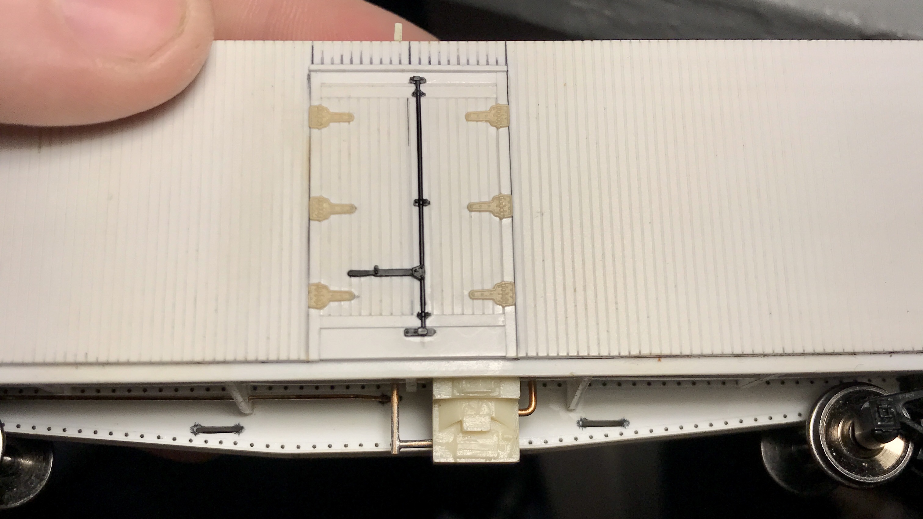
Will the side-sills and centre sills installed in both cars, it was time to make the new ends. For this, I used a 2×10″ styrene strip for the “web” and a piece of 1×4″ styrene on the top and bottom of it to create the flanges. These new ends were glued to the car ends, and I drilled in the holes for the grabs as well. At this point, I took the time to install the retainer detail on the car’s side and placard and defect boards as well as the car’s “end caps,”; all with .005″ styrene.
With the construction of both cars primarily completed, the only remaining significant structural details to add were the brake staff, cut bars, coupler pockets, grab irons and stirrups.

Before priming the cars, I used Archer rivet decals to complete the look of the scratch-built car sides, ends, and new cross-bearers.
After the cars were primed with Tamiya Fine Surface Primer, I painted them with my go-to mix of Vallejo Model Air paints for CN #11 red. I masked off the decking and sprayed the decks with Tamiya Wood Deck Tan, and once all of this had time to dry, it all got a coating of Vallejo Gloss Varnish.
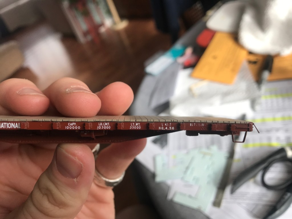
The cars were then lettered using the data charts from the articles. Since both cars were from different orders, they required different data, which needed some cobbling of the Black Cat Decals. Once I was satisfied with the lettering, the cars again got a coat of Vallejo Gloss and then Matt.
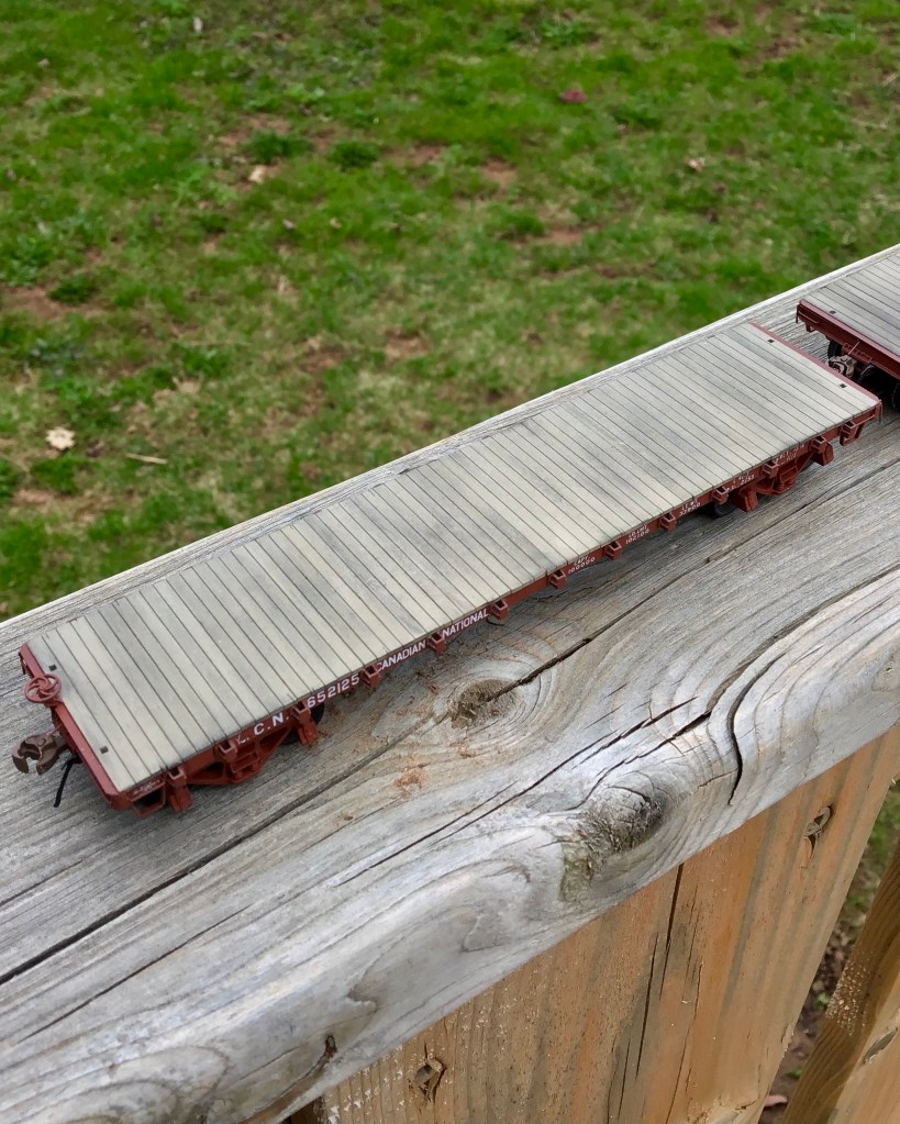
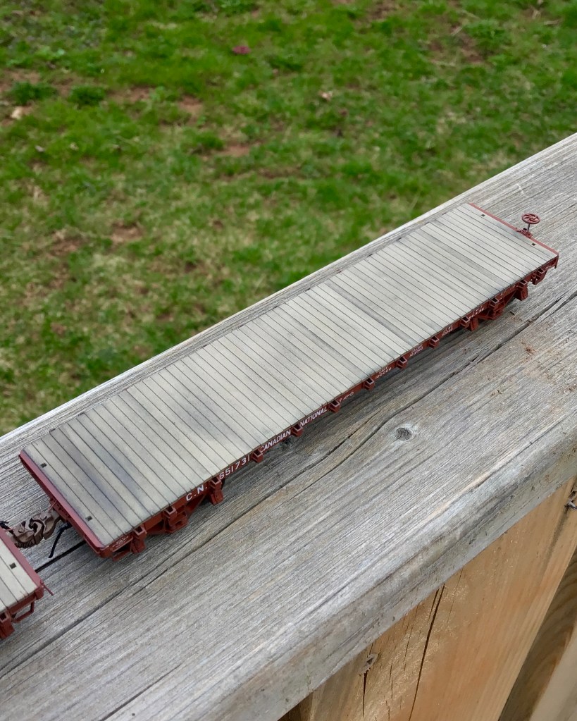
Pan pastels were applied to the decking using the same method I described in my previous post. I did this time, however, have a happy accident. After applying the initial coating of pastels, I decided I overdid it and went to wash them off the car. While I was gently scrubbing the decking with my thumb while holding the vehicles under the sink, I realized this actually created just the effect I wanted, so I stopped washing the pastels off and let the cars dry as is before giving a final coat of Vallejo Matt. After the matt dried there was only one final detail to install: rubber air hoses by Hi-Tech Details.

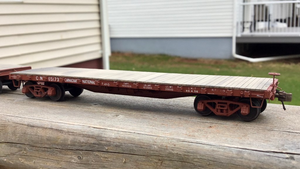
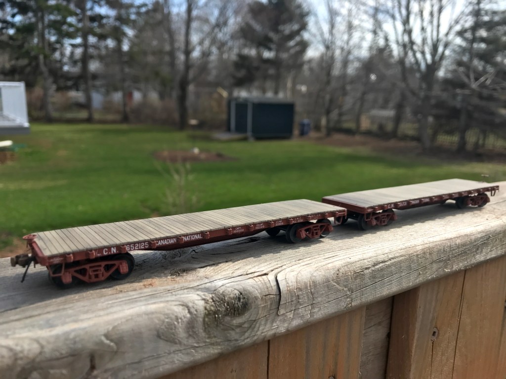
Overall I am very satisfied with how these two flat cars turned out.
I have already begun a scratch build of a “Group C” car, which is already well along and should be the subject of a blog post soon / someday.
C