It’s not often I post about anything ready to run on here, but I think my most recent acquisition is a good exception.
On a night not too long ago, instead of sleeping, I was cruising around through my PEIR files looking at pictures, as I often do.
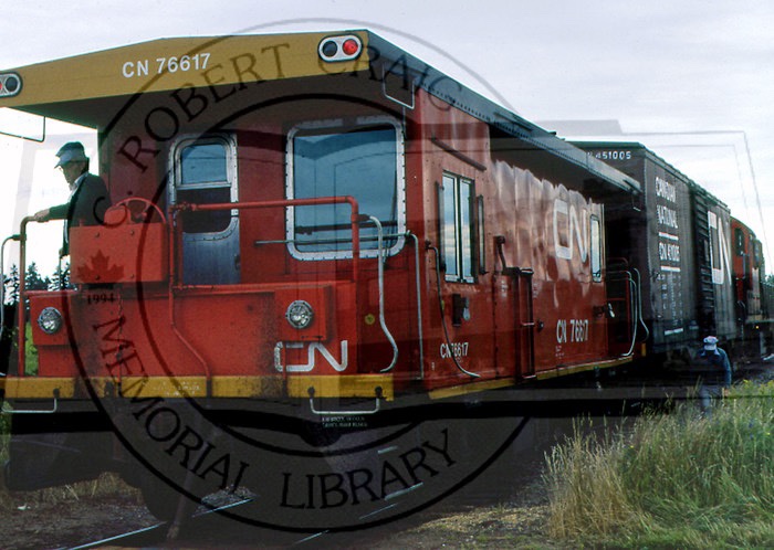
I was about to turn in when I stumbled across a beautiful David Othen photo I’d never noticed before of RSC-14 #1751 hauling a classic PEI train consisting of three boxcars and transfer van #76617 at O’Leary dated June 1982.
While I unfortunately do not have the right to post the David Othen photo here, this watermarked photo of Van #76617 from the C. Robert Craig Memorial Library is from the same era and location as David’s.
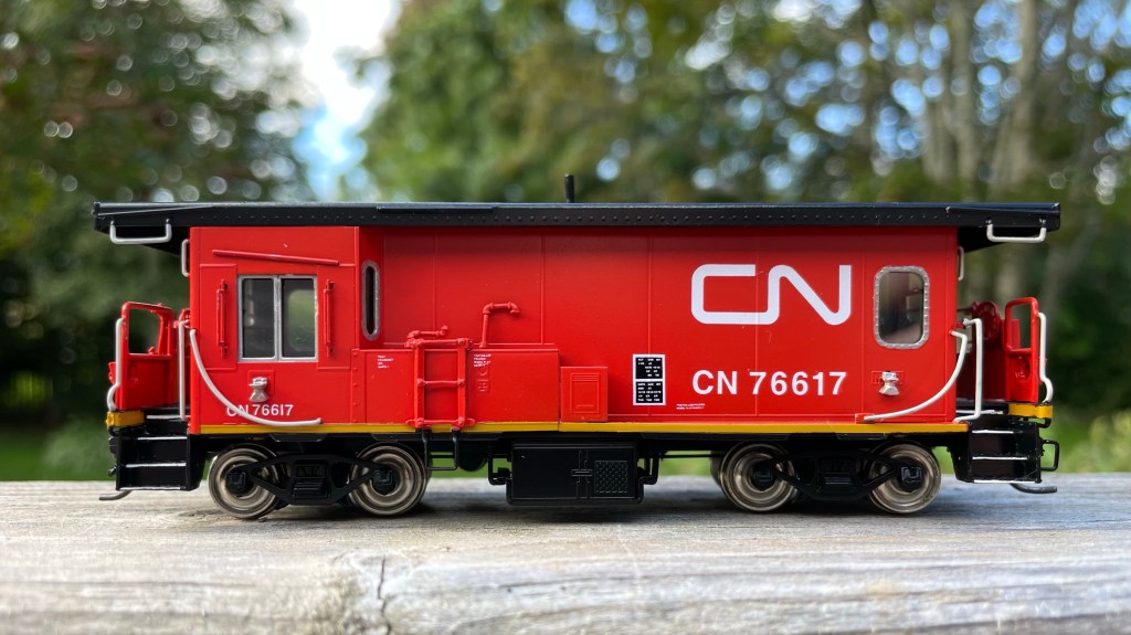
The following day on break at work, I came across a Facebook post by Otter Valley Railroad of pictures of a brass estate they had just brought in and when I saw the green box with “CNR Transfer Van” on the sticker I thought it was probably meant to be.
When Hilda at OVR wrote me back to tell me the model was still available and that if I wanted, they could have David Browning, who used to paint for Overland, paint it for me; I knew it was meant to be.
#76617 arrived late last week, and I am thrilled with how it turned out. It will look great behind RSC-14 #1751 when the Rapido models are finally released.
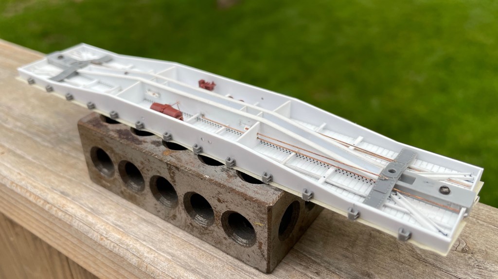
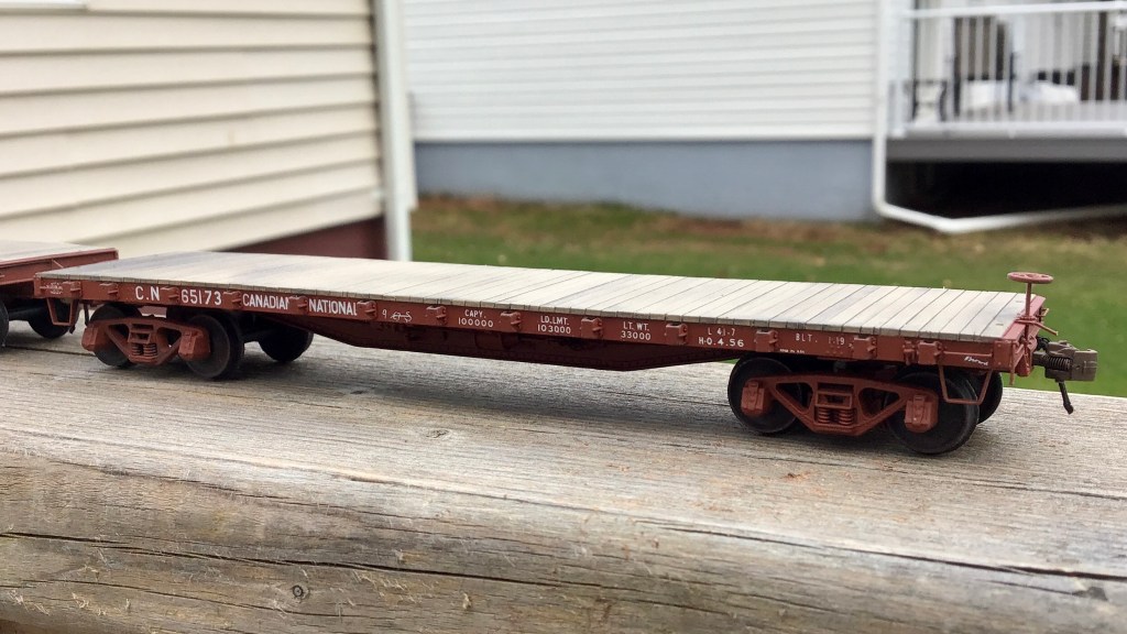
In my last update, I mentioned that my scratch-build of one of CN’s 1929 built “Group C” flat cars was drawing to a close. I am happy to report it is indeed now complete, sans a retainer valve. As I could never discern the valve’s location on the prototype, my thoughts were that it would be better to leave the part off the model entirely rather than guess and find out later it was put in the wrong location.
Let’s begin.
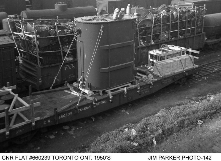
In 1929, CN had 300 46’1″ flat cars built. What makes these 300 cars unique was they were the first flat cars CN had built to its own design. Until this time, all of the flat cars on the CN roster were a hodge-podge of assets inherited from its predecessors, from varying builders and designs.
I learned about these “Group C” cars while working on my CN “A-3” cars: scratch-bashes of two Tichy kits; they are featured in the same two 1994 articles by Stafford Swain in CN Lines (issues V5N3 and V5N4.)
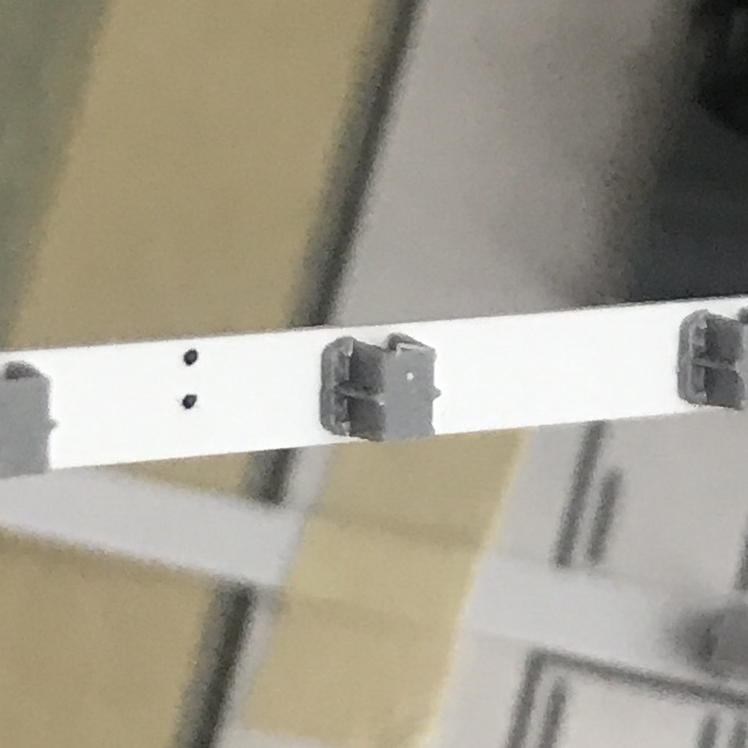
Using the supplied drawings, I cut out a piece of .060″ V-Groove styrene to act as the car floor, and from a sheet of .030″ plain styrene sheet, cut out the side and centre sill plates. The centre sill of the car was then assembled as a sub-assembly, using strip styrene for the bracing, spacing and to simulate the rivet plates. I also added the rivets to the center sill at this point using Archer Fine Transfers, as I knew I wouldn’t be able to get at it after all of the details and side sills were installed.
I took a piece of plain paper, taped it to a piece of glass and then measured out the distance between each stake pocket for the car side sills. I then taped the side sills onto this and glued each Titchy stake pocket to the side sill using the paper as a guide. After the glue had ample time to dry and the styrene had time to properly re-solidify from the solvent glue, I used a #17 blade to take all of the “U bolt” details off the stake pockets. I used the #17 blade to notch a horizontal line across the middle of the face of the stake pocket. Utilizing the notch in the middle of the front of the stake pocket as a guide, I used my flush cutters to cut a roughly 45-degree angle from the center of the face of the stake pocket down to the bottom “foot.” This mimics the prototype more accurately than the Titchy pockets that come from the package. After the stake pockets were completed, I set them aside.
[As you can imagine, the entire process for the stake pockets was an absolute nail-biter because one mistake would render the whole side sill junk… I took a lot of time to make sure I did this cleanly and accurately. I luckily only made one small mistake, which was easily hidden with some Mr. Surfacer 500 painted over the dent in the sill and sanded flat.]
Before installing the centre sill, I drilled out two holes for each truck at a spacing of 35’9″. I then screwed two Titchy Bolsters to the car floor and cemented them in place. Once the cement dried, I fit the scratch-built centre sill snugly between the bolsters, centred it to the car and glued it in place.
The car mostly assembled, but before the final installation of rivets and decking.
I installed Z-bracing to the car floor parallel to the centre sill. The z-bracing was scratch-built by threading two 1×3″ and one 1×2″ piece of styrene through a homemade jig and glued with Tamiya Ultra Thin. Then I used my JMC Micro Saw to cut out notches to fit in the four more prominent cross members, pre-drilled to accept the train line.
The article didn’t include any photos or drawings of the underframe, so I studied the rivet patterns on the car sides from prototype photos and similarly built flat cars to conclude the location of the cross members and brake components.
The fourteen Z-shaped cross members were installed using leftover z-bracing. I notched out one end of each cross member with a 400 grit PC board file to fit flush against the centre sill. I then ran a sanding block vertically down the side of the car floor to ensure there was no overhang into where the side-sills would be installed.
Next, I installed brake levers fabricated from strip styrene into the sill and the Cal-Scale brake parts. This required me to modify the triple valve mount with a file and make hangers for the air tank from phosphor bronze wire.
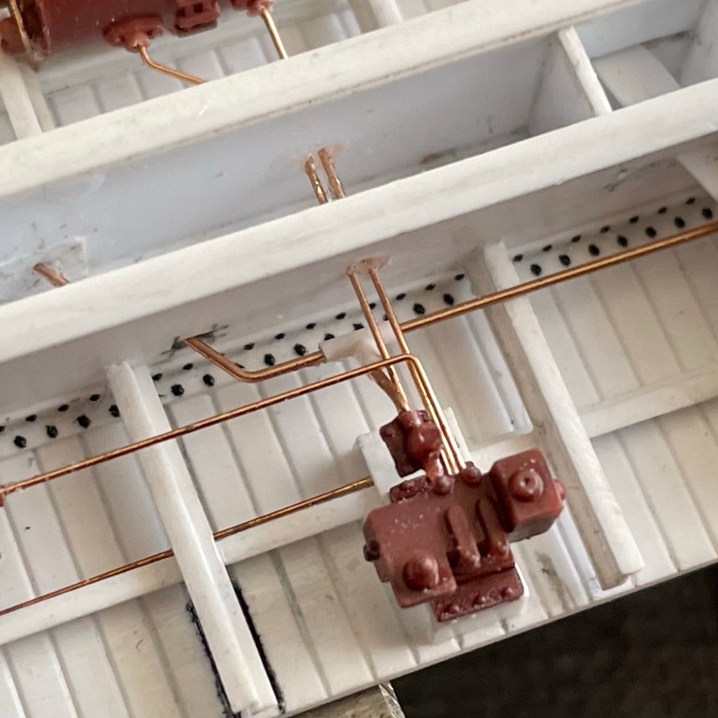
Before installing the brake piping and rods, I scratch-built a slack adjuster from scrap pieces of styrene and used a Titchy NBW to simulate the bolt into the associated brake lever. The airlines were installed with .010″ wire and the rods with .0125″ respectively. I used Titchy turnbuckles cut in half to act as the clevis on the connections to the brake levers, and scale chain was used between the brake cylinder and associated rod. The last thing I installed on the underframe was the train line, using .015″ wire and a scratch-built “t-valve” from styrene rod, connecting the train line to the triple valve.
Close up shot of some of the under-frame detail, including the t-valve.
While this might seem like a disjointed way to go about building the under-frame of the car, I did it in this order because I knew once I put the car’s body sills on, I wouldn’t have much room to work on the small parts. I had to be careful not to box myself in.
With the under-frame assembled, I next installed the side-sills. To get an excellent 90-degree joint, I used a machinist square on its fat edge to push the sill flush while the glue set. The car ends were installed using 1×12″ scale strip styrene and reinforced from behind with 1×10″ to prevent warping.
The joints were sanded clean, and then corner irons were installed with strip styrene.
I used a single edge razor blade to shave the poling pockets off some spare Titchy boxcar ends I had lying around. I glued the poling pockets on top of the corner irons and purposely used a liberal amount of styrene cement so they would melt into the corner irons to look like one solid part.
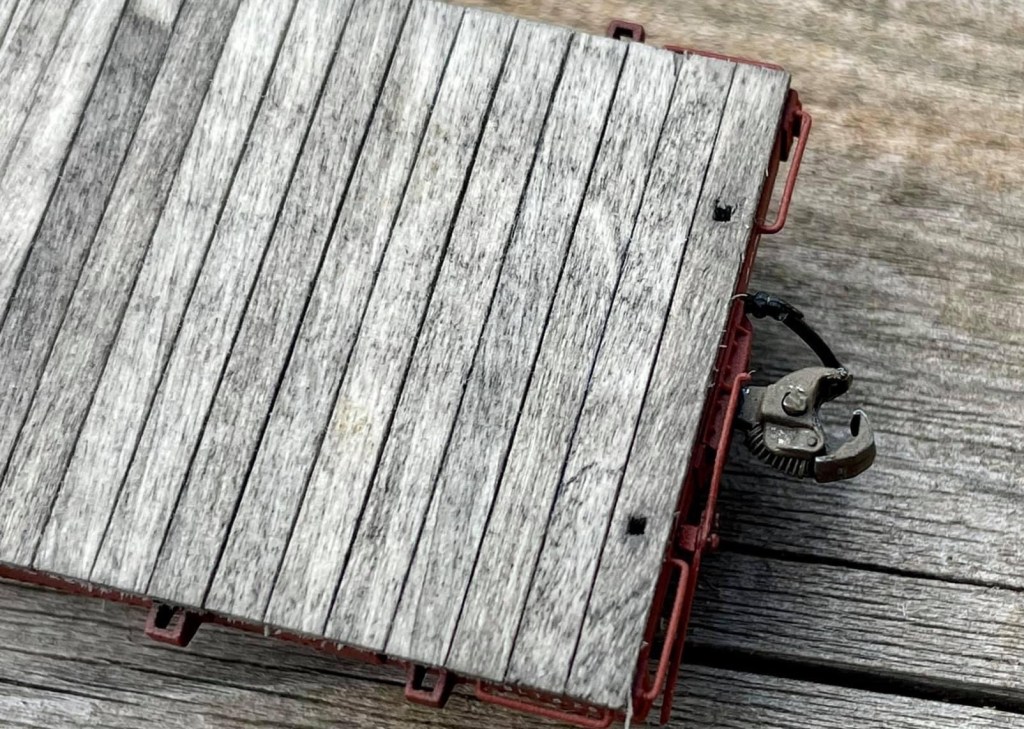
With the general shape of the car completed and the underframe more or less entirely assembled, it was now time to install the Smokey Mountain scale coupler pockets.
I measured the centre of the car ends and then cut notches for the width of the draft gear box with my JMC saw. I scored the inside of the car end that was to be removed with a #11 blade and then snapped it out with my tweezers.
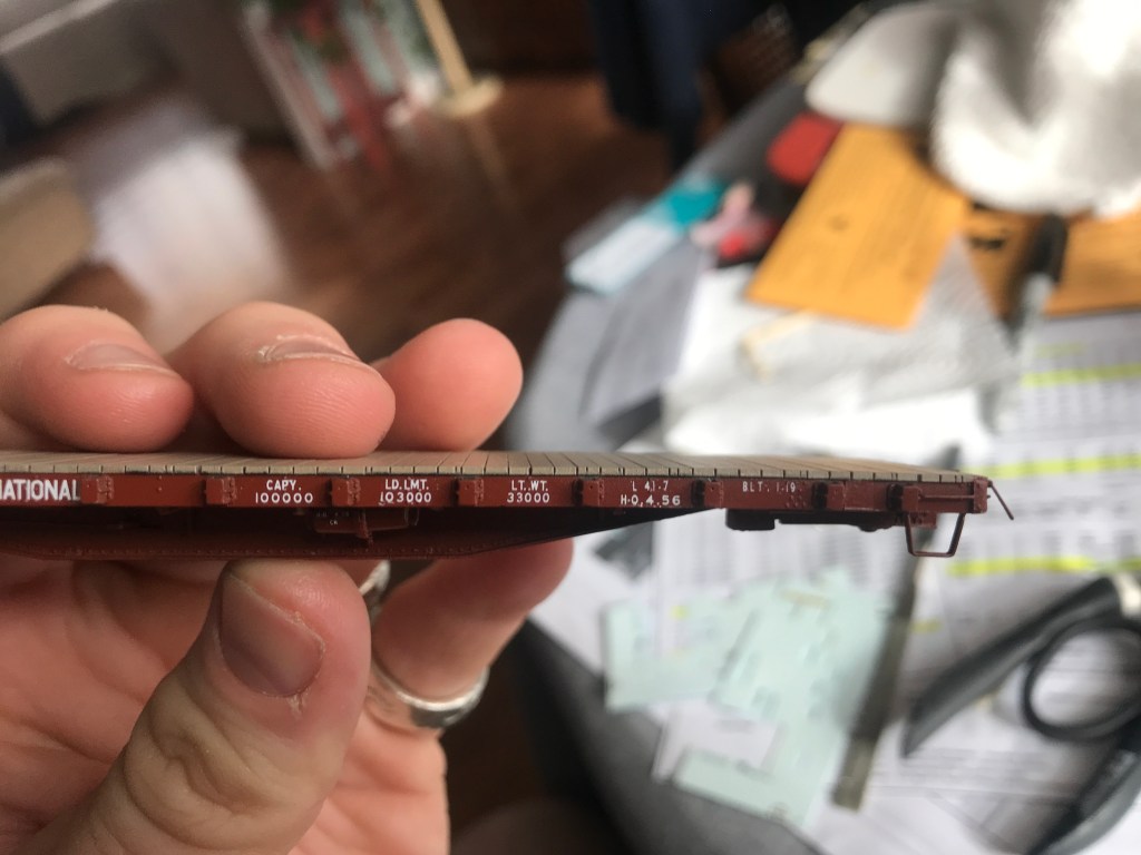
This shows the addition to the buffer plate.
The Smokey Mountain coupler pockets were fitted into the car ends, the screw-hole marked with a pencil and then drilled out and installed. As the prototype had a slightly wider buffer block than the Smokey Mountain product, I used a 1×3″ styrene strip on each side of the buffer block on the car end. This also covered up any visible slop between the draft gearbox and the notch cut out for it.
The brake wheel and its mechanism were installed on the car end. I used the Titchy rachet part but decided to upgrade to a brass Precision Scale brake wheel.
The Yarmouth Model Works Carmer Cut Levers were then installed. I used a 4×4″ square of styrene to mount the cut lever, and put a Titchy NBW on top of it to simulate a bolt.
The grab irons were drilled out and installed with .010″ wire, my new go-to over .0125″ as I find .0125″ looks large when painted.
The A-Line stirrups were held over a candle and flattened out straight, re-bent to match the prototype and then installed by first drilling into the bottom of the side sill before being glued in place.
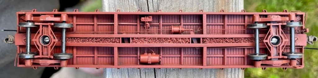
Before painting, I installed all the remaining rivets onto the car using Archer Fine Transfers and the articles drawing as a guide and then installed the Tahoe Model Works Trucks. I also at this point installed the weight into the center sill, which was lead shotgun shot given to my by a friend.
The car was then primed with Tamiya Fine Surface Primer and allowed to dry overnight. I used my regular mix of Vallejo paints to paint the model CNR #11 red. Future floor polish was used to prepare the model for decals.
Black Cat CNR Flat Car decals were applied with the car being lettered for road number #660213, coated again with future floor polish. The car was matte-coated with Vallejo Matt Varnish.
It was then time to install the car’s decking; for this, I used 3×8″ scale lumber from Northeastern Scale Lumber cut into 9′ lengths. I began by first installing a single board on each end of the car, ensuring they were dead centre to the car. After the (15 minute) JB weld had dried overnight, I set a ruler against the boards previously installed on each end and on top of the stake pockets; this created a dead straight line between each back of the car and allowed me to install each board dead center as well. This is an aspect of the build I spent a lot of time thinking out before tacking, as I knew that if the boards waned and weren’t straight, I would not be happy. It turned out to be a straightforward process in the end.
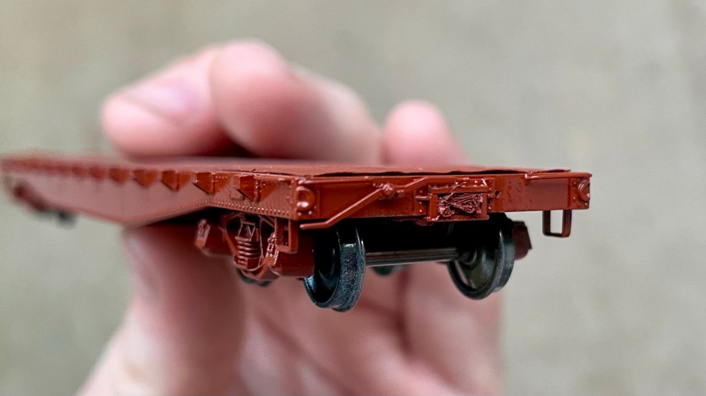
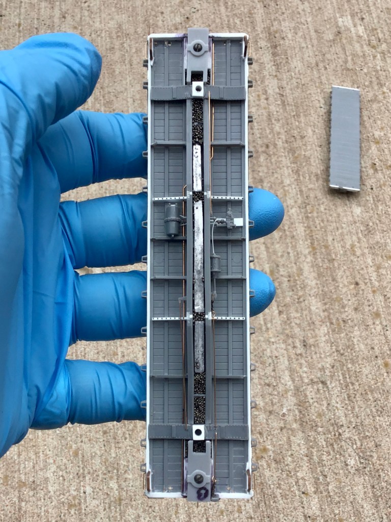
Close up detail of the cars under frame.
Lastly as far as the decking installation was concerned, I drilled out the holes for the end stake-pockets and squared them up with a #11 blade.
With the decking installed, I took a sanding block with 400 grit sandpaper on it. I sanded the deck to level it out a bit and get rid of any fuzzies from the wood I didn’t get before installing. I stained the wood decking on the car with a light mixture of India ink and isopropyl alcohol.
I decided I wanted to try simulating the nails that hold the decking to the car floor. For this, I went to a pharmacy and asked for some of the smallest hypodermic needle tips they had. I measured out where each “line” of nails would be on each end of the car and then used the hypodermic needle against a ruler to install over 400 “nails” into the car deck. I then gave the deck another coat of stain, sanded it, and then stained it one final time. The result is subtle, but I think it turned out well as the nails in a wood deck aren’t that noticeable on the prototype once the deck becomes dirty.
Close-up shot of the completed decking, including the subtle nail details.
Finally, Hi-Tech Details rubber air hoses were installed on each end of the car along with Kadee #158’s.
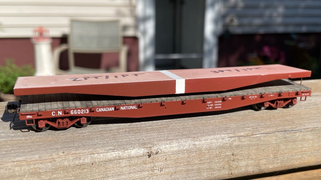
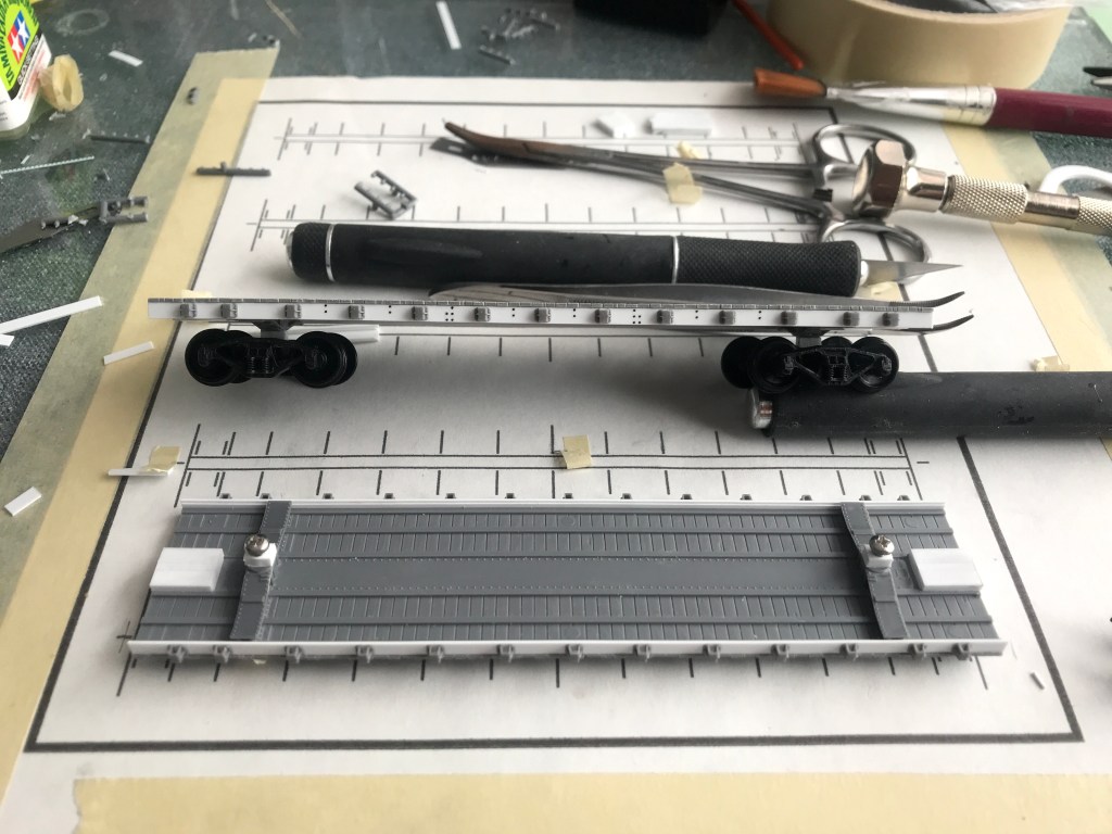
The completed model on the bottom vs the mock-up I made prior to deciding to proceed with the project. The “stripe” in the middle of the mock-up separates two different paint formulas I was testing at the time for #11 red.
That’s a wrap! A long and complicated build is finally completed, and I am very proud of the end result. It is my intent to eventually have this model judged toward an NMRA car-building merit award. Find below a parts and materials list for this build.
Next up, finally more work on that pesky CNR wood-reefer scratch-build (and maybe a new not-so-much scratch built reefer project…..)
CM
RAW MATERIALS:
Evergreen Scale Models:
.060” V-Groove Siding (#14060) [12”x24” sheet, special ordered]
1×2” HO Scale Strip Styrene (#8102)
1×3” HO Scale “ “ (#8103)
1×4” HO Scale “ “ (#8104)
1×6” HO Scale “ “ (#8106)
1×8” HO Scale “ “ (#8108)
1×10” HO Scale “ “ (#8110)
1×12” HO Scale “ “ (#8112)
2×12” HO Scale “ “ (#8212)
4×4” HO Scale “ “ (#8404)
.030” Sheet Styrene (#9030)
.040” “ “ (#9040)
Northeastern Scale Lumber:
3×8” HO Scale Lumber (#3811)
Plastruct:
.010” Styrene Rod (#90850)
Tichy Train Group:
.008” PB Wire (#1100)
.010” “ “ (#1101)
.0125” “ (#1106)
.015” “ “ (#1102)
COMMERCIAL PARTS:
A.A.R. 22” Air Hoses, x2 / Hi-Tech Details (#6038)
AB Brake System, x1 (Plastic) / Cal-Scale (#283)
Barber S-2 50 Ton Trucks / Tahoe Model Works (#113)
Jim Parker photo courtesy of CanadianFreightCarGallery.com – Click for link
At an operating session not so long ago, my friend Derwin asked me if I’d ever considered building a kit for somebody else; and if I’d make a Sylvan CNR Automobile Boxcar kit (HO-1078) for him.
I’ve had a lot of fun operating on Derwin’s “Canadisle” layout over the years, and I thought building this car would be a fun way to give back. Additionally, Derwin models the late 70’s and early 80s, which allows me to explore another era with no commitment. I decided to break from my Group C flat-car scratch build for awhile and put together the kit.
[Note that I don’t currently have any intention of changing my period of focus, although I do have 4 Rapido RSC-14s on pre-order, but I digress.]
Derwin didn’t have a specific road number in mind, so I cruised around on the Canadian Freight Car Gallery until I came across an excellent Jim Parker photo of #740215 in June 1980, right in the middle of Derwin’s era, and decided this would be the one to model.
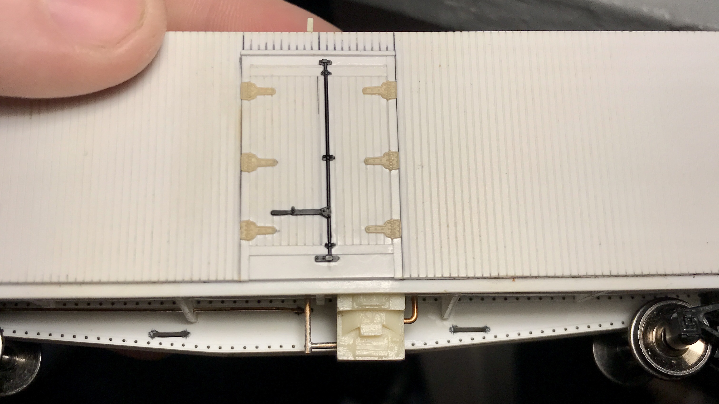
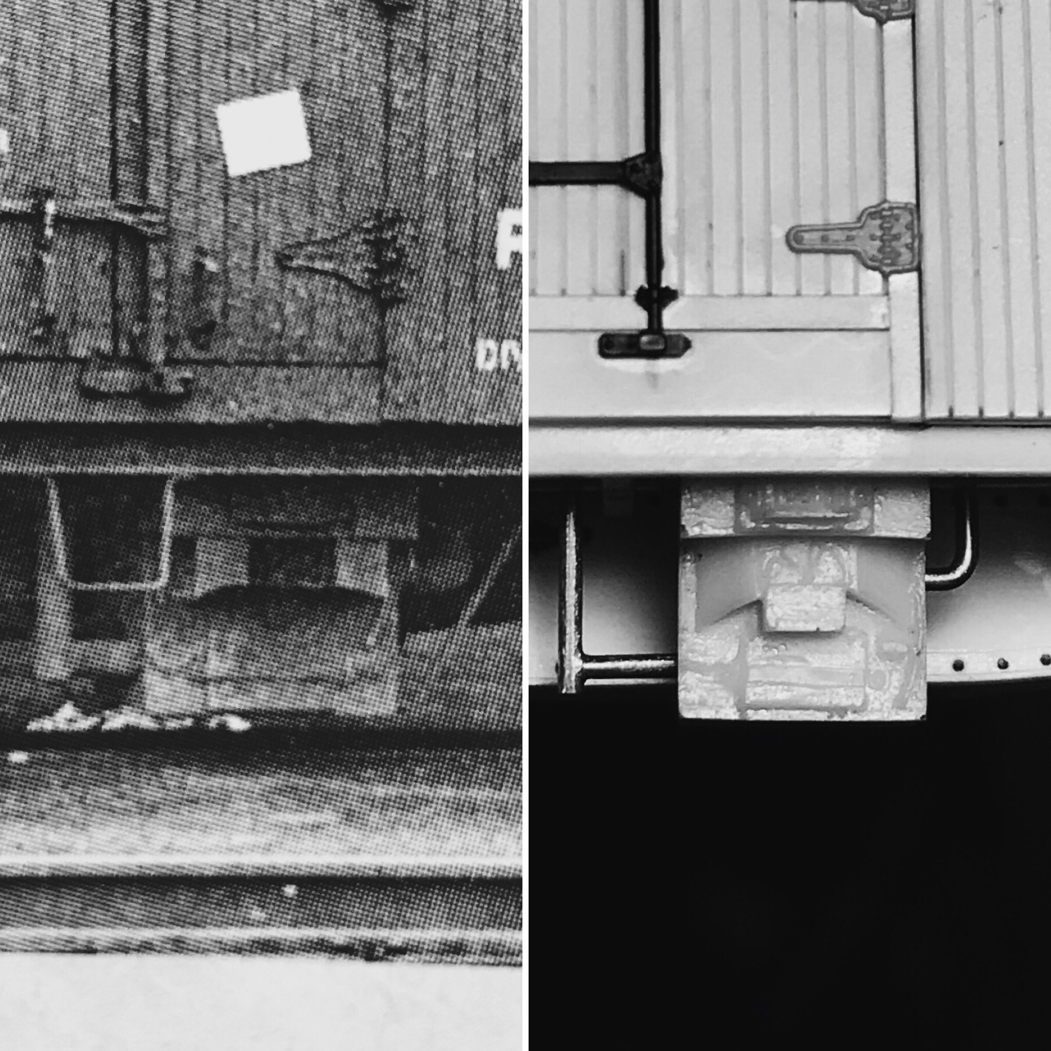
The completed model, from the same view as the prototype photo. Note the simulated “remnants” of the ladder brackets I added to the top of the car body, mimicking the prototype.
The car is built entirely to the kit’s instructions, except for the prototypical differences such as the removed running boards, cut end ladders on the “A” end of the car and a few upgraded parts, such as Des Plaines Hobbies 8 Rung Canadian Ladders, A-Line stirrups, cut levers and Cal-Scale brake details. Derwin also supplied Tahoe Model Works trucks with Intermountain wheelsets, my suggestion.
The car was primed with Tamiya FSP Oxide Red, pre-shaded and painted with Vallejo acrylics, gloss-coated with Future Floor Polish, decals applied with the included Black-Cat Decals (+ Highball ACI Labels and National Scale Car Chalk Mark) matt coated with Vallejo Matt varnish. The matt coat was followed by a very light mist coat of white to simulate paint fade and then sprayed again with Vallejo Matt varnish.
Closeup of the cars brake-wheel and remaining lateral running-board.
Close-up of the cut ladders on the end-door end of the car. Note the simulated ladder brackets towards the roof of the car, remnants of the original full-sized ladder.
View of the underbody brake detail.
Prior to paint.
Primed and pre-shaded.
I’m pleased with how this project turned out, and it was a lot of fun to explore a different era for change. This model was the first I’ve ever applied a noodle decal to, let alone an ACI label!
I’m happy to have been able to contribute to Derwin’s layout, even if it’s a small piece of it, and with that in mind, I built this car as if it were for myself.
Calvin
PS: That Group C flat-car scratch build is coming to a close; post coming soon!
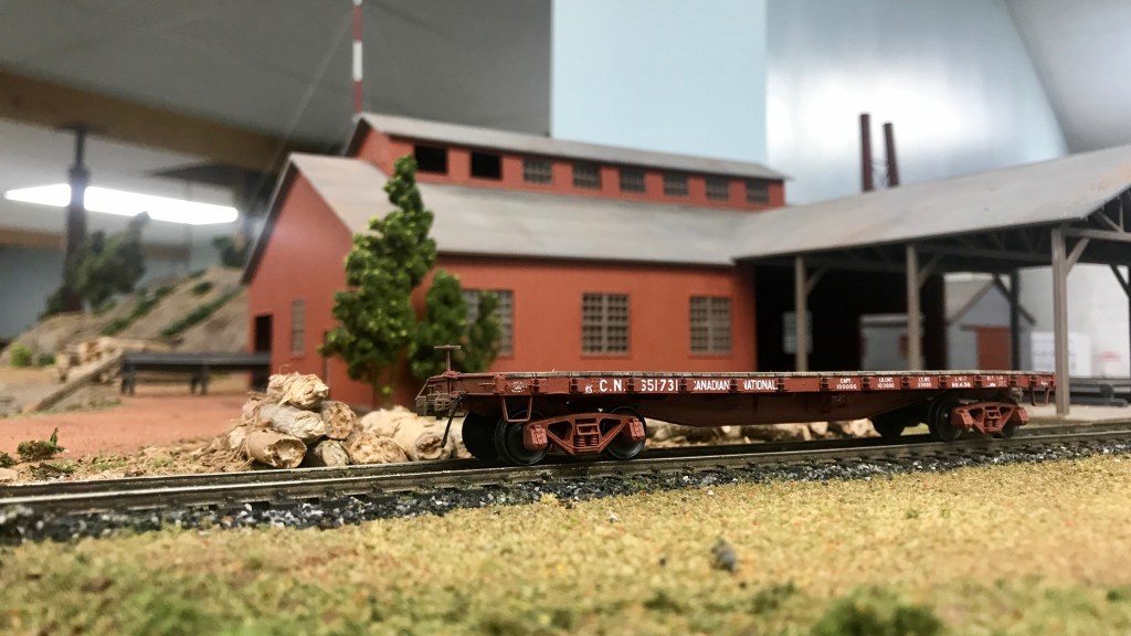
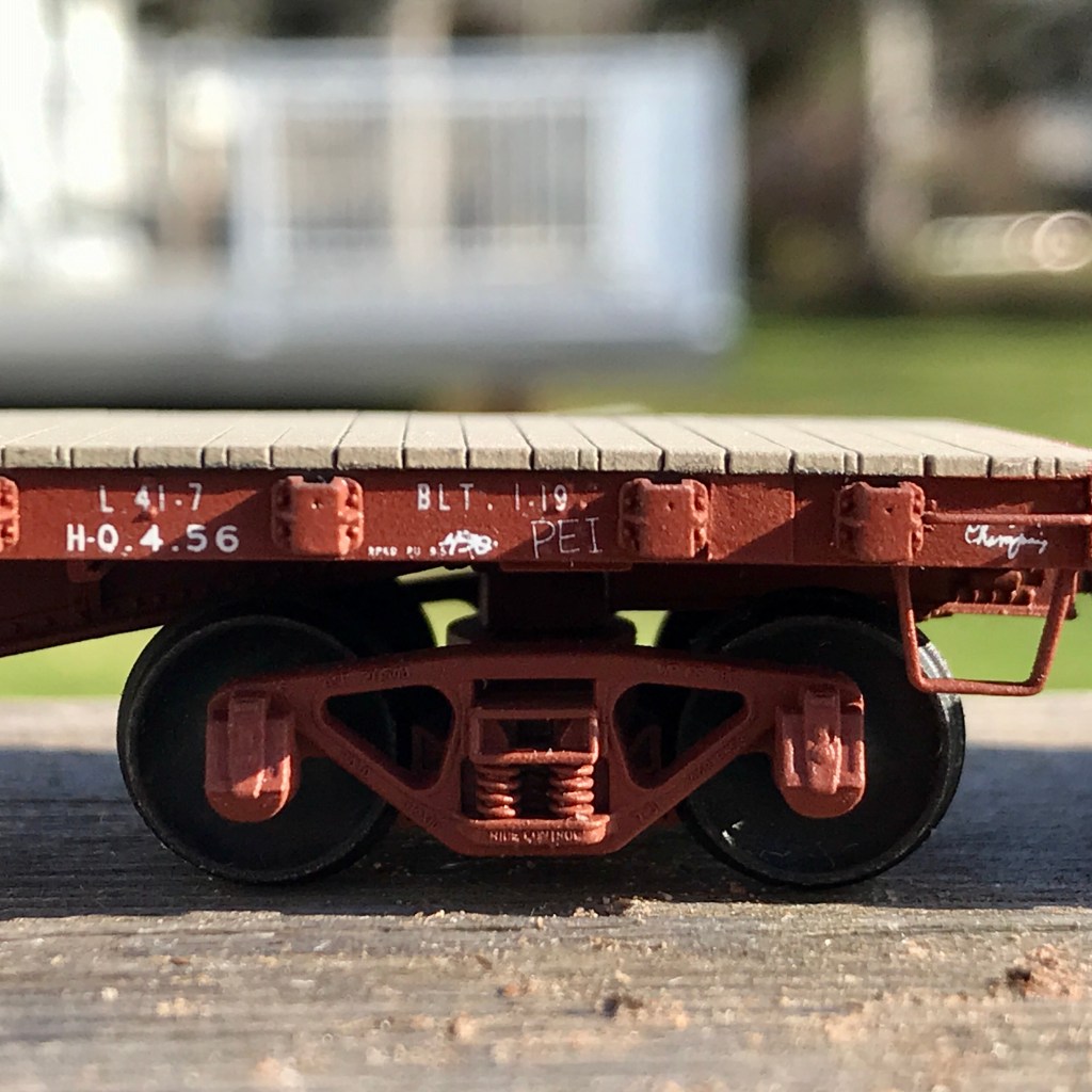
CN #651731 – BLT. 1.19 for the CNoR in Trenton, NS, sold to CN in the 1920s, is seen on spot at the sawmill on Trevor Delaneys yet to be named layout. We are so lucky to be doing as well as we are in terms of COVID-19 in PEI; we are allowed to have indoor gatherings of up to ten people, which allows us to continue to have operating and work sessions for the time being.
In the early 1920s, during the founding years of the Canadian National Railway, a wide array of freight and passenger equipment was inherited from its predecessors. Amongst these inherited cars was a venerable fleet of flat cars of steel construction, initially built for Canadian Northern Railway (CNor), Canadian Government Railways (CGR) and Grand Trunk (GT).
These steel cars were the subject of a duo of Stafford Swain articles entitled “CNR Pre-War Steel Flat Cars – Part I” [CN Lines Vol 5, N3 – focuses mainly on prototype information] and “CNR Pre-War Steel Flat Cars – Part 2” [CN Lines Vol 5, N4 – focuses primarily on building the cars in HO scale, includes scale drawings].
As I’ve mentioned before, you can buy a thumb drive that contains every single back issue of CN Lines, and these two articles were worth the price alone.
The articles cover the A-1, A-2, A-3, A-4, B-1, B-2, C-1 and D-1 series cars- all of which can be built with relative ease from Tichy #4021, Athearn donor cars, or just straight up scratch-built.
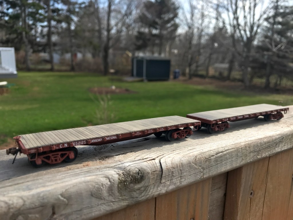
I decided to build two “A-3” cars: #651731 from the CNor order and #652125 from the CGR order, using Tichy #4021 as a starting point. Both orders were handled by the Eastern Car Company of Trenton, NS, just 66 kilometres as the crow flies from Vernon River, PE, in the winter of 1918 / 1919.
I began by first installing 2×8″ styrene strip substrates in substitution for the kits supplied side sills. Next, I raised the height of the car by 6″ by first installing the kits provided truck bolsters and then a 6″ styrene block at the pivot point of the bolster. I also added a 6″ styrene block where the coupler pockets would later be installed.
At this point, I used a CAD program to create and print a template to aid in the positioning of the stake pockets on the scratch-built side 1×10″ sills. The spacing measurements for the stake pockets are provided in Stafford’s article.
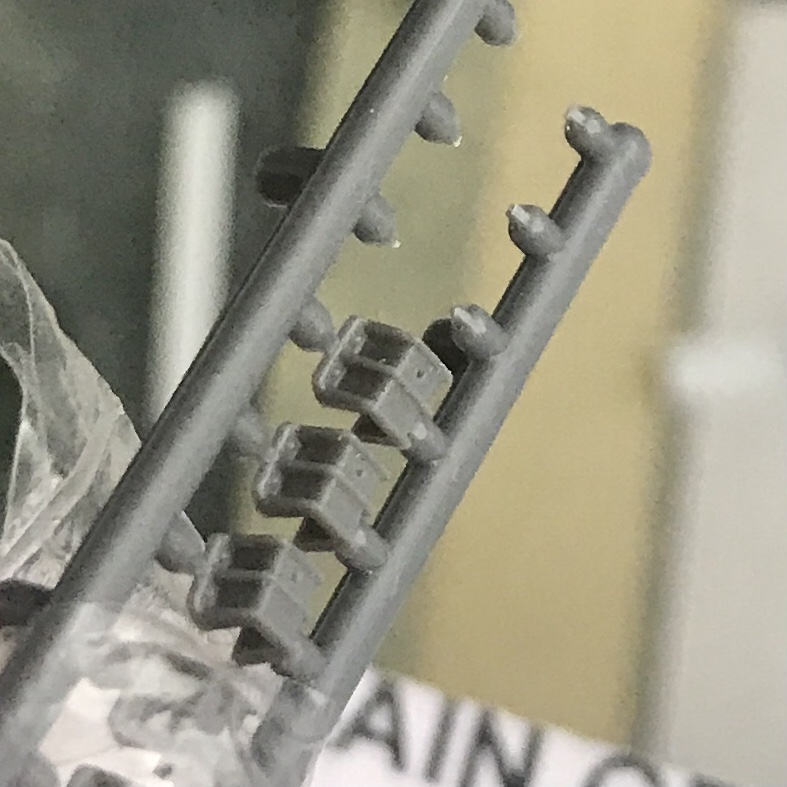
The stake pockets as supplied.
The stake pockets after modification.
The kits provided stake pockets are inaccurate for the CN prototype as supplied. This was remedied by filing off the details on the front of the pockets while still attached to the sprue. After this was done, I used the previously mentioned template taped to a sheet of glass to aid the placement and installation of 13 stake pockets per sill.
Once I had 4 side sills created, and I was sure the glue was dry, I went back with a #17 chisel blade and removed the remaining “u-bolt” details from the top and bottom sides of each stake pocket. With all of these details removed and a coat of Tamiya Extra Thin styrene cement quickly applied over the entire pocket to dissolve any leftover detail fragments and “melt” everything together, the stake pockets now more closely resembled the cast metal pockets of the CN prototype.
With the significant structural work of the side sills complete, I glued them to the car and then drilled out the holes for the grab irons. At this time I also drilled out end pockets in the cars decking. To clarify: the reason I used a 2×8″ strip for the substrate and then 1×10″ for the actual sill was to create the illusion of a more “thin” side sill if the car is viewed from track level while still maintaining the overall thickness of the kits supplied sills.
Visible are the guide sheet I made along with the new side sills and the styrene blocks used to raise the height of the car.
Next, I began work on modifying the supplied centre sill.
I began by filling in the notches in the kits sill sides that normally accept the kits’ super deep cross-bearers. After these “notches” were filled in with styrene and filed level, I installed the centre sill.
After the centre sill was installed, the next task was to establish an AB brake system and its piping in place of the kits provided K system. Because all of the drawings in the article have the K system, I had to turn to prototype photos to figure out where everything went. I mounted the brake cylinder to the mounting bracket for the K system, and then with a prototype photo, figured out the location of the air tanks. With these two locations known, it was easy to extrapolate the location of the triple valve.
I added the kits provided weight at this time and also added some lead shot in an attempt to add even more weight to the car. The prototypes more shallow cross-bearers were fashioned from sheet styrene and installed. (Again, the measurements for the replacement cross-bearers were in the article.)
Center sills with bottom notches filled in.
Will the side-sills and centre sills installed in both cars, it was time to make the new ends. For this, I used a 2×10″ styrene strip for the “web” and a piece of 1×4″ styrene on the top and bottom of it to create the flanges. These new ends were glued to the car ends, and I drilled in the holes for the grabs as well. At this point, I took the time to install the retainer detail on the car’s side and placard and defect boards as well as the car’s “end caps,”; all with .005″ styrene.
With the construction of both cars primarily completed, the only remaining significant structural details to add were the brake staff, cut bars, coupler pockets, grab irons and stirrups.
The cars prior to priming.
Before priming the cars, I used Archer rivet decals to complete the look of the scratch-built car sides, ends, and new cross-bearers.
After the cars were primed with Tamiya Fine Surface Primer, I painted them with my go-to mix of Vallejo Model Air paints for CN #11 red. I masked off the decking and sprayed the decks with Tamiya Wood Deck Tan, and once all of this had time to dry, it all got a coating of Vallejo Gloss Varnish.
Lettering in progress.
The cars were then lettered using the data charts from the articles. Since both cars were from different orders, they required different data, which needed some cobbling of the Black Cat Decals. Once I was satisfied with the lettering, the cars again got a coat of Vallejo Gloss and then Matt.
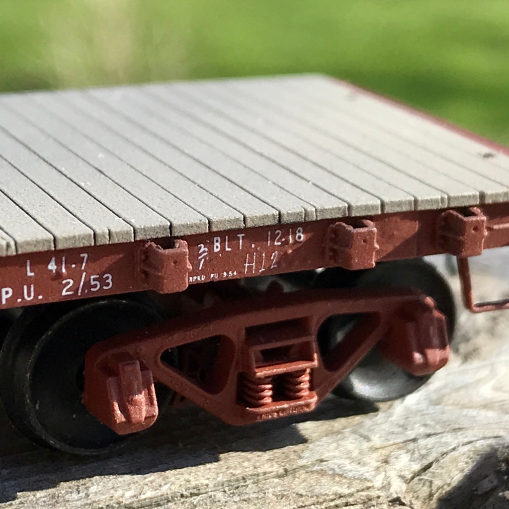
Some fun was had with National Scale Car and Microscale chalk decals. “H12” was the actual switch identifier for the Vernon River public siding. (Note the decking is pre-weathering.)
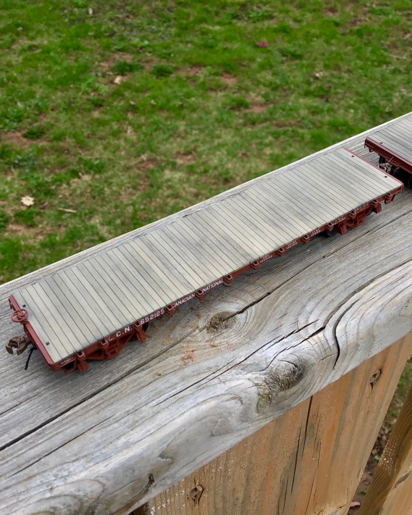
Lightly to moderately weathered decks achieved by applying pan pastels and then partially washing them off.
Pan pastels were applied to the decking using the same method I described in my previous post. I did this time, however, have a happy accident. After applying the initial coating of pastels, I decided I overdid it and went to wash them off the car. While I was gently scrubbing the decking with my thumb while holding the vehicles under the sink, I realized this actually created just the effect I wanted, so I stopped washing the pastels off and let the cars dry as is before giving a final coat of Vallejo Matt. After the matt dried there was only one final detail to install: rubber air hoses by Hi-Tech Details.
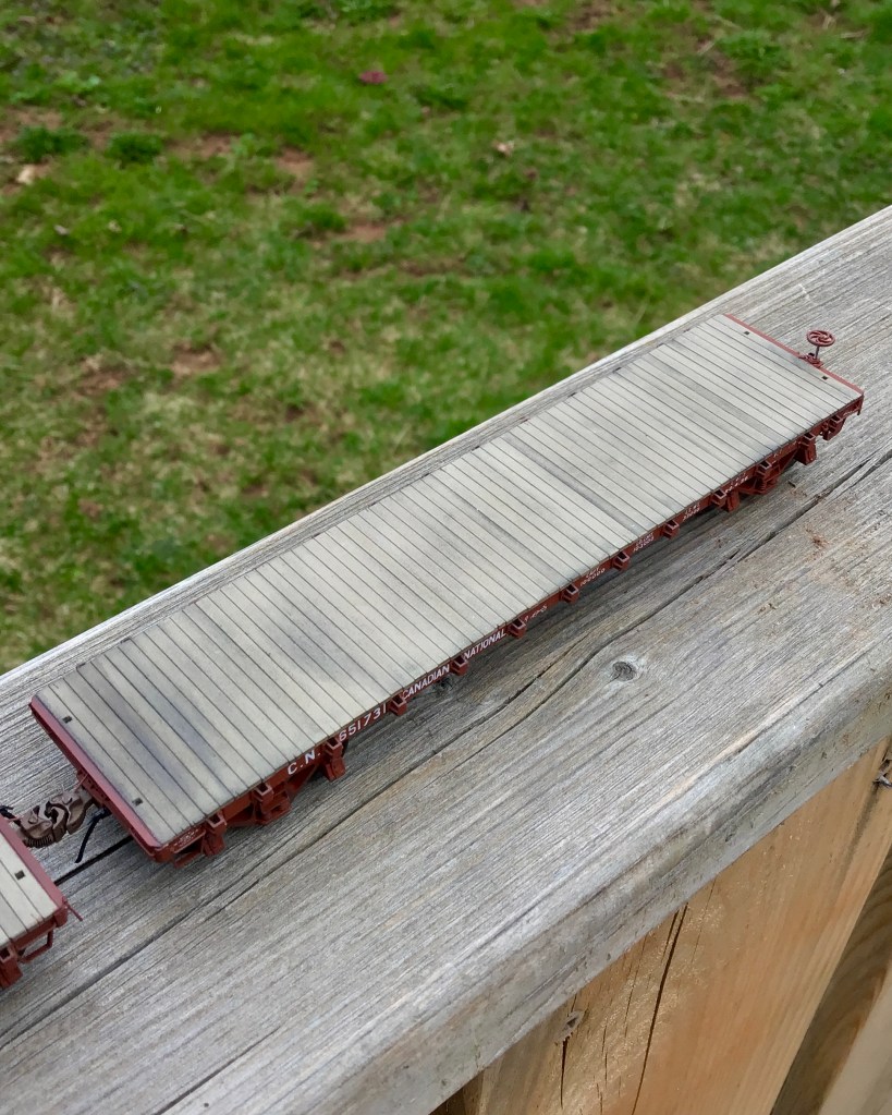
Overall I am very satisfied with how these two flat cars turned out.
I have already begun a scratch build of a “Group C” car, which is already well along and should be the subject of a blog post soon / someday.
In the last minutes of 2020 I sat, bored, at my work bench and decided to start a Tichy 4021 kit I had on hand.
My original plan for the kit was to modify it to be a CNR A-1 Pre-war Flat car, as outlined by Stafford Swain in CN Lines V5 N3- but as will be revealed below that didn’t happen. (But has since happened with a couple other kits, which will be covered in a future blog post.)
I was so into the build that I decided to just build the kit as it was for once, not worrying about making it accurate or performing any major surgery.
This was a nice thought as I built the kit, however after I finished the construction I realized that it’s inaccuracy would bother me if lettered for CN.
So, I began the hunt for a railroad that ran a car close in construction to the Tichy kit as built.
What I came across was the Central of Georgia, whose historical society is restoring a flat car very similar to this, and is even selling Tichy kits packaged with the correct trucks and CG decals with all proceeds going towards the cars restoration. I decided this would make an interesting prototype, and ordered some decals.
I painted the car black, with Vallejo “NATO Black”, and the deck with Tamiya “Wooden Deck Tan” – the latter a recommendation from Pierre Oliver’s November 2020 blog post “Flat car decks, a better way?”.
The car as it was before the application of pan pastels. You can see here that I over-sprayed the decals with Nato Black to take the crisp, white newness out of them and add some pre-weathering.
At this point I managed to knock one of the plastic Tichy stirrups off the car; so I removed the rest of them with my spru cutters and replaced them with A-Line stirrups that I had “squared” up by heating them over a candle, flattening them out and re-bending them with chain nose pliers, a Bill Welch technique, and a worthy upgrade to any car.
After I had the car painted and the stirrups fixed, I applied future floor polish with my airbrush and then lettered the car. The lettering makes the car accurate for about 1947, about ten years before my layout at Vernon River takes place- so if it appears on the siding somebody invented a time machine. After lettering, I simply brushed some future over the decals to seal them and then airbrushed the car with Vallejo Matt Varnish- which is now going to be my go-to flat finish.
Again, following Pierre’s previously mentioned blog post I applied pan pastels to the cars deck. This was my first time using pan pastels and man, I love them! They are so intuitive to use, blend super smoothly and are actually pretty hard to mess up.
While this car isn’t even close to being accurate for my era, it’s still an interesting prototype and is fairly accurate within its self. I’m really happy with how this project turned out, and it was a great test-bed for pan pastels. I am still waiting on the proper Andrew’s trucks to arrive, but I’m way to excited to not share the car just how it is.
Coming down the pipe: an update on my CNR Reefer scratch builds, building two Sylvan CNR Wooden Express Reefer kits (just need to be lettered now), modifying two Tichy flat car kits to CNR A-3 Pre-War Flat cars and scratch building a 46’1” CNR flat.
While my blog posting has been lacking, I’ve been building more now than I ever have before. I have 4 or 5 different projects on the go and it feels really nice to be back at it with the passion I had before.
The CNRHA (Canadian National Railway Historical Society) and its magazine, “CN Lines,” are undoubtedly well-known entities within Canadian modelling circles.
However, you may not have known that as of July 1st, 2020, you can now purchase a USB drive containing every single back issue of CN Lines for only $50. I sure didn’t, anyway.
That’s right. EVERY. SINGLE. BACK ISSUE on a USB stick for only $50.
This is undoubtedly among the best $50 I have spent in this hobby as a prototype modeller.
The back-issue USB drive paired with the free online index means that I now have over 32 years of accurate and relevant prototype information gathered within the CN Lines Magazine at my fingertips. This has already saved me a substantial amount of research time on my next project, two CNR 40ft flat cars to serve the Vernon River sawmill, which will be Tichy kits modified using a Stafford Swain article.
If you’re looking for a great source of prototype information as a Canadian modeller, look no further and order one of those USB sticks today.
I have no affiliation with CNRHA; I just can’t get over the value!
As my modelling slowly starts to ramp up again, there isn’t much content for me to post. However, I realized that the projects I completed before this blog’s existence are not yet documented here. I thought it might be fun to fill in the slow times with what I’m going to call a BUILD RUN-DOWN. I felt the right place to start would be with a Funaro & Camerlengo CNR 8-Hatch Reefer kit I built a couple years back.
(Click for source)
Between 1939 and 1958, the CNR had built for it over 3000 8-hatch steel reefer cars. F&C has built flat resin kits to represent these cars for 20+ years. I have a handful of the True Line Trains ready to run models, but I wanted to paint one up with the red maple leaf and #11 red under-frame.
A completed CNR #209667.
The kit was built, mainly adhering to the included instructions. However, I provided some enhancements by upgrading and adding a few details. (I will provide a parts list at the end of the post.)
Construction began by cleaning up all of the flat kit castings and giving them a bath in Dawn Dish Soap to remove any mold release agent.
The truck bolsters on the car’s under-frame were then drilled and tapped, and the same for the couplers. At this point, while the kit was still flat, I drilled out most of the holes required for grab irons, eye bolts and the heater pipes. However, some of the holes were left undrilled until the body was assembled to ensure their placement would be accurate.
Once I was satisfied that I had removed all of the flash and mold release agents from the parts, I used 1-2-3 blocks, tape, patience and a minimum initial amount of CA to assemble the flat car sides, ends and roof into a 3D body shell. At this point, I turned my attention to the under-frame.
Completed under frame.
I used various sizes of Tichy phosphor bronze wire for the brake rigging. My standard approach for this is to use .015,” or .020″ wire for the train line (if I include it), .0125″ wire for the brake rods, .010″ wire for the air-lines and .008 wire for the retainer line and release rod, the latter which I usually wait and add after the model has been fully painted and the underframe has been glued in place. Tichy turnbuckles cut in half were used to simulate the Yarmouth Model Works brake levers’ clevis. The piping going to and from the underslung heater was added with piano wire. (In hindsight, you may have better luck with some Tichy .038″ PB wire as cutting piano wire this thick was NOT fun. I eventually had to use aviation snips.)
This photo shows how I used masking tape marked with lines to properly align the installation of the hatch rests.
Once I was happy with the underframe, I moved to the car body. As I mentioned above, I adhered mainly to the kit’s instructions, so I won’t bother getting too detailed. However, I will say out of all of the upgraded detail parts I used, I think the Des Plaines Hobbies Canadian Style 8 Rung Ladders and Yarmouth Model Works running boards made the most significant visual difference; I can’t recommend these parts enough for your next Canadian prototype build.
The completed car, prior to painting.
The hatch rests, tack + defect boards, brake wheel mount and jacking pads were built with Evergreen strip styrene. This was all pretty straight forward except for the hatch rests. The hatch rests included with the kit left a lot to be desired, so I used a tip I read on Pierre Oliver’s blog and made them out of strip styrene. A strip of 1×3″ and 1×6″ styrene was glued together in an “L” shape, which I then cut to equal sizes with my NWSL Chopper II. To have the hatch rests appropriately centred on the model’s roof, I laid out strips of masking tape on my workbench. I measured out the proper distances and drew lines on the tape to use as a guide, then taped the strips to the roof of the model and glued the hatch rests on with CA using the tape lines as a guide.
These photos show the pre-shading effect. The last photo is how the car looks after the final paint application, over the pre-shading.
I primed the car with Tamiya Fine Surface primer- the bottom section of the car got primed with Oxide Red while the body got primed with Grey. I then loaded up my airbrush with black paint (VMA 71.057) and pre-shaded all of the panel lines, grab irons, brake rigging, running boards— virtually anything I wanted to stand out. I then painted the model, as usual, allowing the pre-shading to very lightly appear through the paint. The car’s bottom was painted #11 Red while the body was painted #11 Grey and all paints were Vallejo Model Air. To get #11 Red, I mixed 2pt VMA 71.105 to 1pt 71.038. For #11 Grey, I used straight VMA 71.045. After the model was painted, I used a #0 brush to paint anything attached to the body but falling under the sill (such as grab irons, stirrup steps etc.) #11 Red.
The lettering process.
Before lettering the car, I sprayed it with Testors Glosscoat and allowed it to cure for four days. The car was lettered with Black Cat Decals [CNR#209710-H] instead of the ones included. I also had some Speedwitch Media freight car chalk markings (highly recommended), which I later added. To get the particular car number and correct data information I wanted onto the model, I had to do some surgery on the decals. I wound up placing a lot of the numbers individually, which was time-consuming. After lettering was finished, the car was again sprayed with Glosscoat followed by Dull coat and allowed to cure.
Another angle of the completed car.My completed kit (right) next to its True Line RTR counterpart.
All in all, I was very satisfied with how this model turned out. I gained a lot of experience and tried many new-to-me techniques.
Next time I’ll be giving a rundown on a Yarmouth Model Works 40ft CNR boxcar I completed a year ago.
Thanks for reading!
CM
COMMERCIAL DETAIL PARTS USED:
“HO Canadian 8 Rung Ladders” / Des Plaines Hobbies [DPH-2003] x1 Package
Laser Cut 40′ Wood Running Board w/ Laterals & Etched Brackets / Yarmouth Model Works [YMW-255] x1 Package
“Eyebolt No Collar” / Yarmouth Model Works [YMW-500] x1
“Eyebolt w/ Collar” / Yarmouth Model Works [YMW-501] x1
“Bracket Grab Drilling Template” / Yarmouth Model Works [YMW-502] x1
“Brake Levers, Set of 10” / Yarmouth Model Works [YMW-503] x1
“Turnbuckles” / Tichy Train Group [#8021] x1 Package
“Straight Side Mount (Stirrup)” / Tichy Train Group [#3038] (included w/ kit) x1 Package (Tip: After all of my upgrades, I do find these are left looking a little out of scale. Perhaps an A-Line product would have been better suited.)
“Freight Car Chalk Markings” / Speedwitch Media [D135]
SCRATCH-BUILT PARTS USED:
Hatch Rests x16 – Scale strip styrene cut with a chopper tool and glued together in “L” shape
Defect Boards x2 – Scale strip styrene cut and assembled
Tack Boards x4 – Scale strip styrene cut and assembled
Drain Spouts x4 – Tichy PB wire inserted into holes drilled into car bottom and glued from the inside. Square styrene strip cored out with a pin vice and then slid over the PB wire, dab of CA secures the styrene to the bottom of the car and wire.
Brake Lines – .010 Tichy PB wire measured, cut to size, bent with pliers, inserted and glued into brake components.
Brake Rods – .0125 Tichy PB wire cut to size and inserted into Tichy turnbuckles which were cut in half and thinned down to simulate the clevis.
Coupler Cut Levers x2 – .008 Tichy PB wire cut and bent to shape. Inserted through bracket on car end and through YMW “Eyebolt No Collar” above coupler.
Release Rod x1 – .008 Tichy PB wire cut and bent to shape. Inserted through hole drilled into sill and through YMW “Eyebolt No Collar”, drilled and inserted into triple valve.
Stand-offs for DPH 8 Rung Ladders x8 – Strip styrene cut and glued to ladders, then ladder glued to car.
Underslung Heater Piping x2 – Music wire cut, bent and inserted through holes drilled into the sides of the underslung heater casting and through holes drilled into the car floor. Glued from the inside of the car with JB Weld 2-Part Epoxy (the 15-Minute stuff)
Small update coming at y’all- and while it’s small, the process behind this was large.
Last night, in the final hours of my 20s, I installed the underslung charcoal heaters and their piping onto Reefer cars’ underframe.
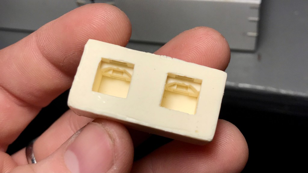
The heaters were resin copies I cast of a certain manufactures underslung charcoal heaters that I could not purchase individually from a kit. I cut a notch out of the previously installed Z-bracing and then affixed the heater right to the car floor with CA.
Heater and piping installed on what will become CNR #209232
The piping was .032” Tichy PB Wire threaded through the car floor into small holes drilled into the heaters. I made the “T” joint by first filing the ends of the cut wire totally flat, then used masking tape to hold the wires together in the desired formation on top of some scrap wood. Flux was applied, and solder was liberally applied to the joint. I cleaned it up with 400 grit sandpaper, rubbing alcohol and a wire brush.
The bracing/strapping that holds the heaters to the car floor on the prototype will be installed after the final under-frame installation is made
One of the first things I had to consider before taking on this project (almost a year ago !!!) was the availability of certain parts that would be rather difficult to scratch build- the big concerns being the roof hatches and the underslung heaters.
Well, I was able to find suitable hatches to use (Details West RH-1003). Still, underslung heaters were going to be a different story.
I tried emailing a certain resin kit manufacture multiple times to see if I could purchase some of their cast underslung heaters that they include in their Reefer kits but received no response.
Second, I took to Shapeways to see what I could find. I placed an order with a certain shop for some heaters that looked promising, but when I received them- though they were nice, they just didn’t look as nice as the other manufacturer’s part. And that just couldn’t do.
So, as a last resort, I raided a couple of unbuilt 8 Hatch Reefer kits I have in the closet, got a casting kit at Great Hobbies and cast my own resin copies of the underslung heaters; something I’d never done before.
I’ll spare the casting process, but I’m happy with how they turned out. And while it was a minor headache to not just buy the parts I wanted, this turned out to be a great learning experience, and I’ve learned a new skill.
[A note on ethics: I wouldn’t condone doing something like this (even for personal use only) if the parts in question were still in print and/or readily available. You should always support hobby shops and manufacturers whenever possible. Don’t be a dink.]
The time has come for the PEIR (Prince Edward Island Railway) to have its own collaborative, indexed, searchable and accessible corner of the internet.
After a few years of on and off thought and consideration, and after seeing one previous attempt: I have taken it upon myself to follow in Steve Meredith’s footsteps (DARdpi.ca / DARwiki) and start a PEI Railway wiki website entitled the “PEIRwiki.”
With the PEIR, I’ve always found that while there is a vast amount of information out there, it’s all quite scattered. When I was new to the interest of railroading, I found this scattering of information daunting.
I want to change that.
I want anybody with even a passing interest in this railway to access detailed, accurate information. I also suspect this will augment my own research in the railway.
So with that said, I present to the world PEIRwiki.ca.
Anybody who is interested in or knows somebody who would be interested in contributing, please get in touch.
Ok. So, before the world exploded my focus in Vernon River land was more or less on preparing for the laying of ties, ballast and track.
For a man who hasn’t even laid flex track before, you could imagine how deep of a daunting rabbit hole this could be.
It has been my full intent since Day 1 with not only this project it’s-self, but my modelling as a whole to hand lay my track. It just seems like the right thing to do and nothing looks exactly like wood, but actual wood.
Instead of just going in blind and starting to lay track on my actual bench work I figured it might be fun / a good idea to teach myself this group of skills by building a display / test track.
So that’s what I did.
I ordered a “Ultimate Track Sample Starter Pack” with Code 55 rail and 8ft ties from Proto87, snagged a 1×3 that a buddy of mine had from his old deck, got some 1/2in extruded foam left over from a different buddy’s garage build and got to work.
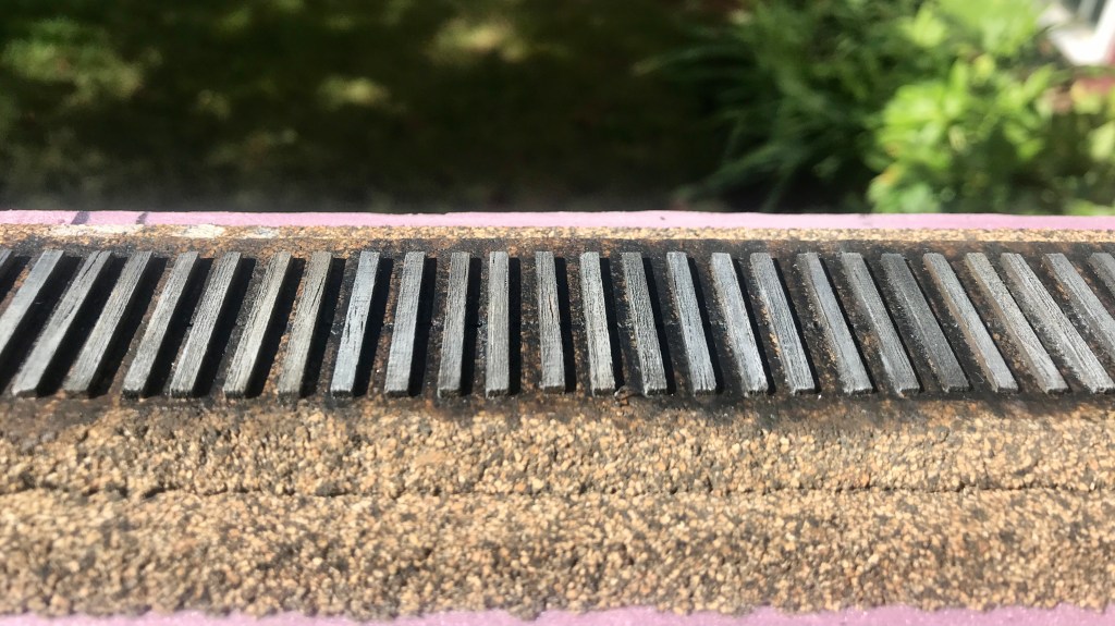
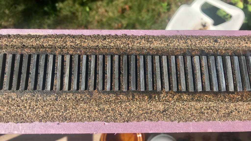
I’ll go over the actual test track it’s self another time. What I want to show off here are my ties.
Hunter Hughson has a great post on Weathering Ties with Acrylic paints over at his blog that I more or less followed to a tee, and man am I ever happy with how they turned out. The only thing I changed from his process was how I went about beating up the ties. Instead of a dental pick, chisel tip and #7 Exacto blades I used a dental pick and wire brush at the suggestion of Chris Mears.
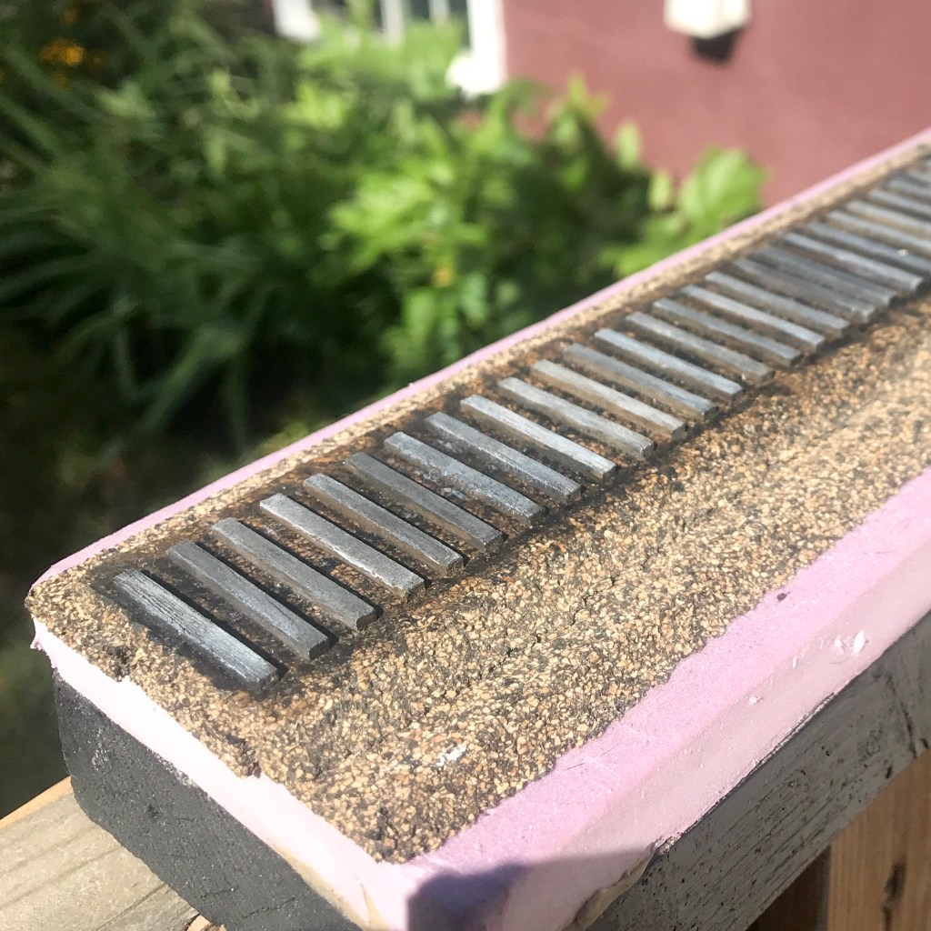
I had the idea to perhaps switch it up and represent a later era with my test track; say the late 70s or early 80s, where tie plates would be more prevalent on the prototype [AKA a excuse to use more of the beautiful Proto87 tie plates that came with the sample pack]. However, I’m leaning back to sticking with the late 50s. I’d still perhaps throw a couple tie-plates down here and there on newer looking ties.
Next up will be ballasting. If I stay with the late 50s it’ll be cinders, if I go with the late 70s / early 80s it’ll be a mix of crushed rock.
Telling the stories of the history of the port of Charlottetown and the marine heritage of Northumberland Strait on Canada's East Coast. Winner of the Heritage Award from the PEI Museum and Heritage Foundation and a Heritage Preservation Award from the City of Charlottetown